AVR ASM bit-bang UART Tx routines
Here are some serial UART transmit routines that I have come up with. They're probably not perfect and certainly leave some room for improvements, but they're a start.
- suitable for probably all of the Atmel (now Microchip) ATtiny- and ATmega-AVRs
- written in assembly, as I still don't grok C
- no need for a hardware USART, thus works with tiny's just fine
- not based on interrupts and thus easy to implement (must not be interrupted though)
- everything 8-N-1 only
- just put the byte to be sent in variable tmp and rcall one of the routines
- most of the implementations go faster than the hardware UART
- most of the implementations allow to minimize the error rate by using irregular baud timings
- different implementations optimized for small code size, high speed, high throughput, low register usage
- fastest implementation can achieve 1.8432Mbaud on a 1.8432MHz clock, or 19200baud with -0.4% error on a 32.768kHz watch crystal resonator
Overview and Description

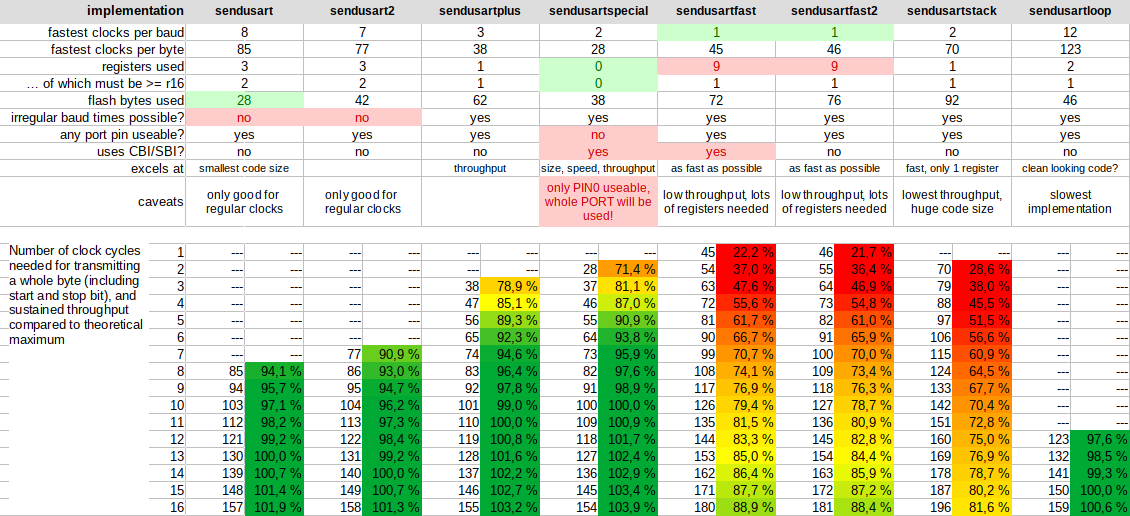
The table above lists all the relevant traits of all the implementations. Most of the rows should be pretty much self-explanatory. ''fastest clocks per baud'' tells you how fast that routine can go; a 10 here means that each baud needs 10 clock cycles. So if you're running at 1MHz clock speed, the theoretical maximum would be 100kbaud.
The next line lists how many clock cycles the whole routine takes for sending a whole byte including start and stop bit. From these two values you can derive the sustained throughput that is possible (the lower part of the table list some examples). While the fastest implementation is able to achieve 1.8432Mbaud on a 1.8432MHz clock for a single byte, it has some overhead to prepare the buffers and needs some additional time before it can send out the next byte. In this example that would be 46 clocks total for 10 clocks of actual data, taking some 25µs, yielding some 40kiB per second instead of the maximum achievable ~184kiB/s. Maximum throughput is thus only ~20%.
''irregular baud times'' refers to the possibility of easily skewing the baud time for each bit individually. Here's an example: You're running your AVR on 1MHz with CKDIV8 programmed, for an effective clock speed of 125kHz. A baud rate of 14400 translates to a baud time of 8.68 clock cycles per baud; using a regular 9 clocks per baud leads to an error of 3.55%, which is pretty high already. Instead of using 9 clocks for each baud, you can now use 8 and 9 clocks in sequence, like this: Start bit 9, eight data bits 8 - 9 - 9 - 8 - 9 - 9 - 8 - 9, stop bit 9. Set up the routine for a regular 8 clocks and add a nop to the corresponding bauds to hit a 9. This will reduce the total error to an excellent 0.22%, while the slight jitter should be inconsequential.
''any port pin useable'' tells you whether you can pick any port pin you like. This is true for all but one implementation. The routine will read the corresponding port and make a change only to the selected Tx pin, leaving the other pins of that port unaffected. The only exception here is the ''sendusartspecial''-routine, which directly writes the whole data byte to the whole port. In this case you will have to use PIN0 of that port as your Tx pin, as that will be the only pin to receive all the bits in the correct order. The routine works by writing the whole byte at once, which takes one instruction, then does a logical shift right (through PIN0), taking another instruction, and then repeat this another 8 times. This way we can achieve high speed while still maintaining a pretty good throughput. The obvious downside is that you should not use the remaining 7 port pins for any critical output duty (some indicator LEDs might be okay, showing some occasional flicker; you decide).
''uses CBI/SBI'' refers to the use of those instructions. For probably most of the different AVRs out there, those instructions will take two clock cycles to execute. My routines were written with those devices in mind. The newer cores, most notably the X-types, will only take one clock cycle though, so you'd have to adapt the code to that. Refer to the AVR instruction set manual, which contains a list of all the AVR devices and corresponding core architectures, if you're unsure and cannot get away with one of the other routines.
Overall I'd prefer the ''sendusartplus''-implementation. It does use more flash memory than the loop-based routines, which may become a problem, but otherwise it is the fastest and most well-behaved one without any other major quirks. In case you're wondering how it manages to achieve more than 100% throughput: The routine ends immediately after setting the stop bit; if you now fetch the next byte to send (easily done in only one instruction) and call the routine again, it will already set the next start bit before the whole baud time of the previous stop bit has passed. You will have to take care of this yourself, depending on how you are going to use the routine. You'll be safe when using any of the options with 10 clocks or below though.
Calculating Baud Rates
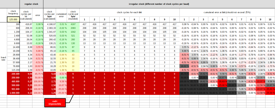
Since WormFood's AVR Baud Rate Calculator won't cut it in this case, I've created myself a simple spreadsheet for LibreOffice Calc. Just enter the controller's clock speed top left, and pick whichever one of the possible baud rates suits your application best.

Might look a bit intimidating at first, but it's not that bad actually. We'll start to the left, where you will find a list of several standard baud rates. Everything colored dark red would have to be faster than your clock is and can be safely ignored. The next two columns under the header ''regular clock'' will show you how many clock cycles you'd need for any given baud rate, and the error you'd achieve if you used the next integer value. Let's again pick 14400 as an example: 8.68 theoretical clocks would round up to 9 practically achievable clocks, yielding the indicated error of 3.55%. How much error is tolerable in your application will depend on several things, but as a rule-of-thumb I coloured everything bigger than 2.5% in red, lower than 0.5% in green and the intermediate in yellow.
The next few colums will show the clock cycles for a whole byte (i.e. 10 baud for 8-N-1) and this time the cumulated error for an irregular clock. Right next you'll have ten columns showing the exact clock cycle count for each of the ten bauds. These are the values you'd want your Tx routine adjusted to, by strategically inserting some nop's. If all those 10 values are equal, you're good to go and use a simple regular clock routine instead.
Further right you'll find some additional information on the bit error, or jitter. Note that this error number is different from the previous errors and thus colored differently. Imagine this as 10 equally spaced time slots; if you were to deviate more than 50%, you'd be reaching into the adjacent slot and that won't work, obviously. I have somewhat arbitrarily set 25% as an upper limit, implying that 10% should be somewhat okay.
- ''tx_uart_bitbang.asm'' - all the implementations in a single file
- ''tx_uart_bitbang.ods'' - LibreOffice Calc file