Ulti-Preamp
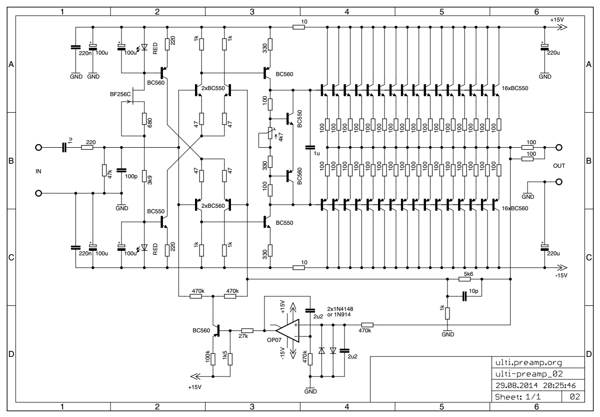
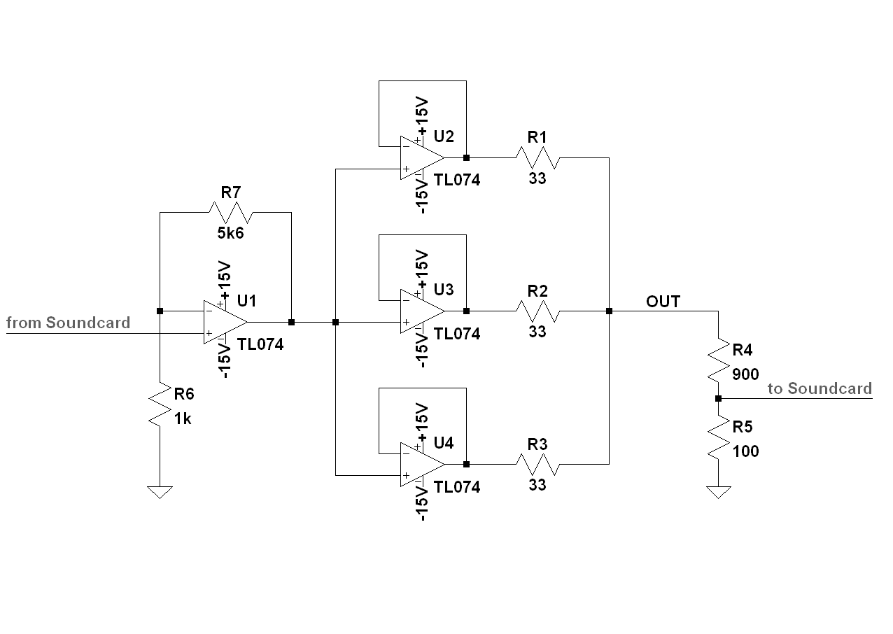
The corrected schematic
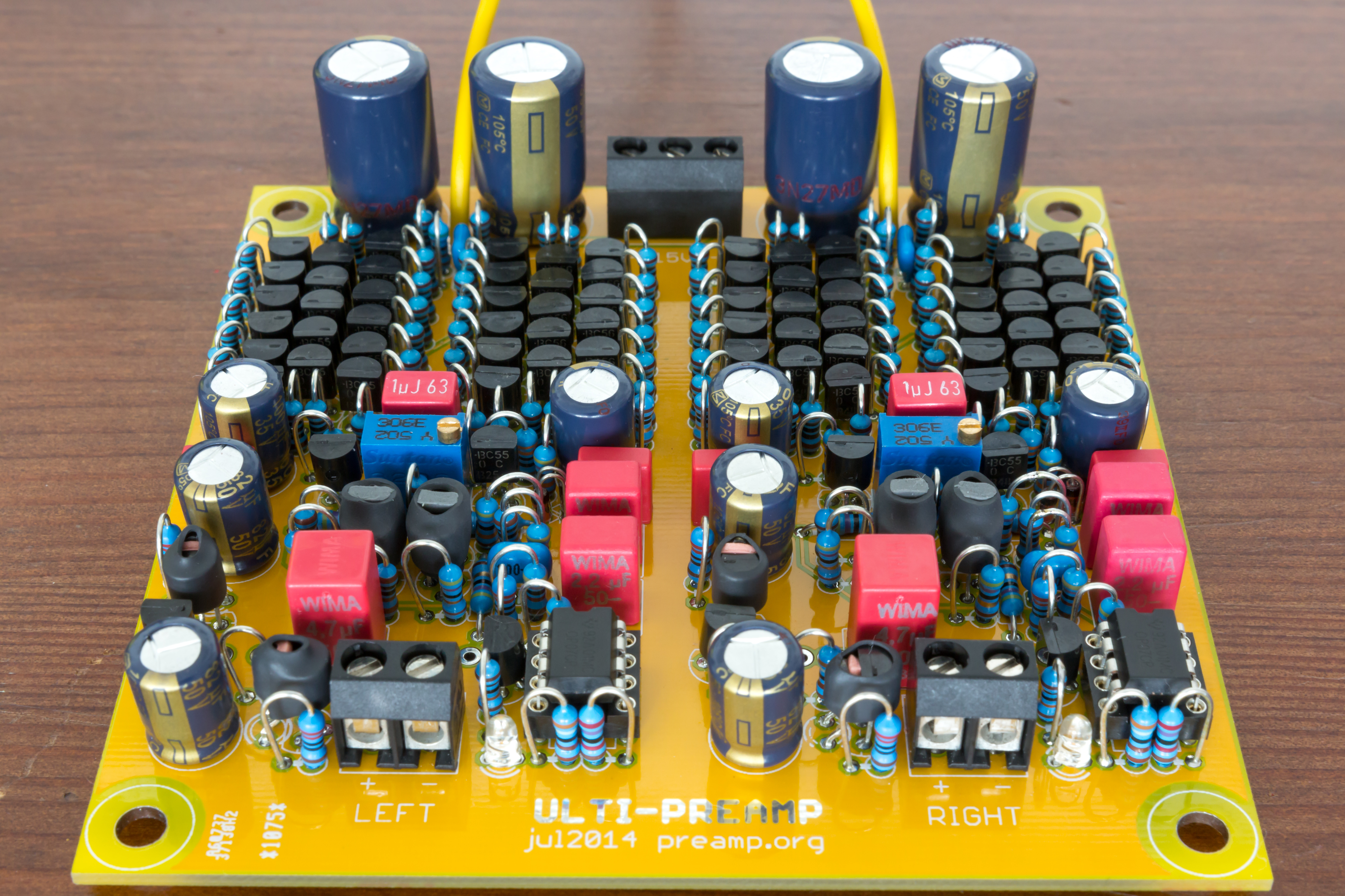
The ''ulti.preamp.org'' is a discrete preamp and headphone amp constructed with standard parts. The circuit is based on the '94 ulti preamp published by Elektor. I have made some major changes though, which I'll describe now.
First of all, I wanted to get rid of the hard to get and pretty expensive dual transistors. They're obsolete for a couple of years now, but you can still get them (or some of their successors), but they're still pretty expensive. For the price of one dual transistor you can get a whole bunch of BC550 and BC560, 100 each in my case. This way you'll have to match them yourself, but the money you saved buys you all the other parts you need to complete the amp :) .
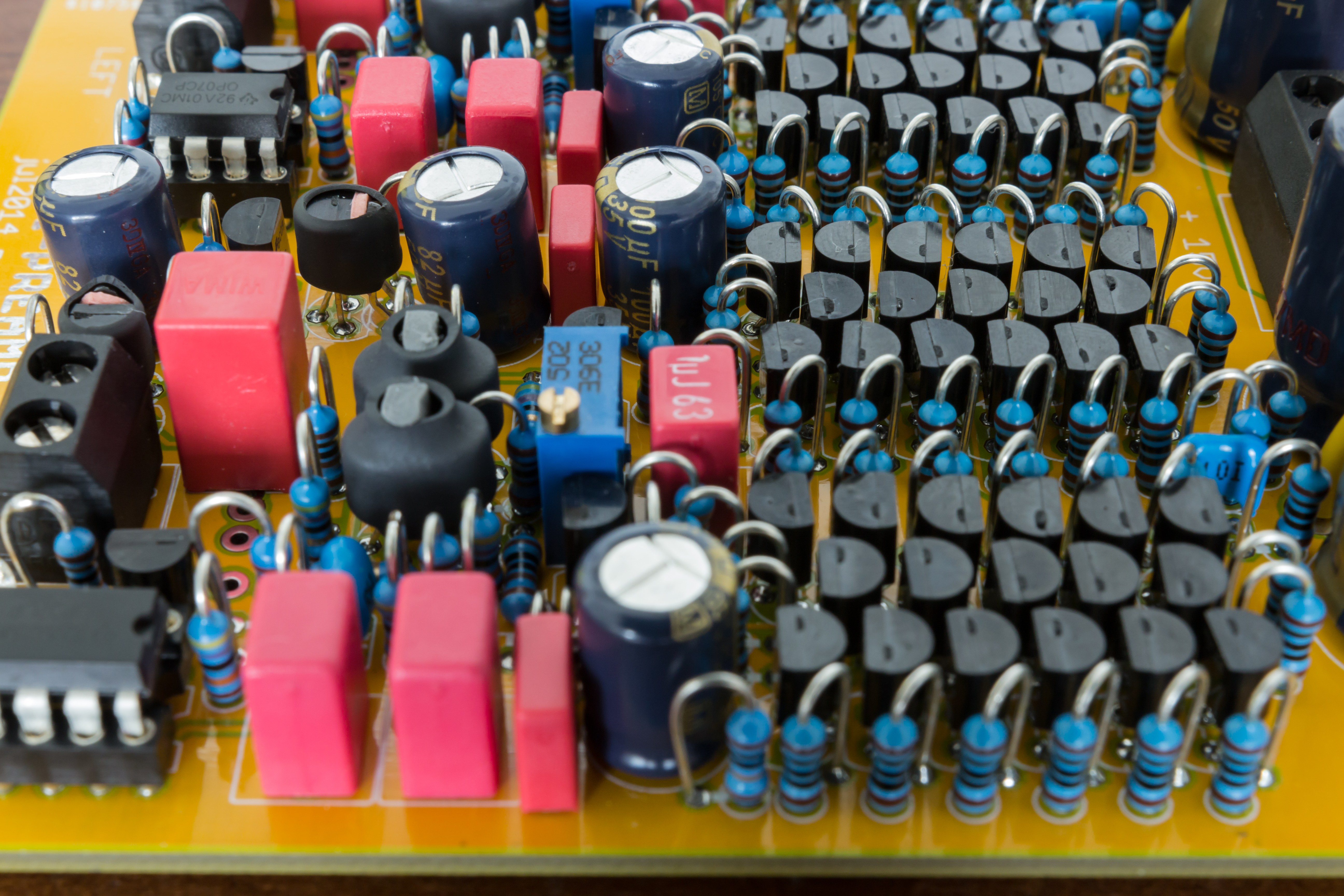
And here's the next point: I wanted to make use of the remaining 192 transistors. That's why I swapped the output stage transistors with 16 individual ones, each. Turns out to work pretty well :) . Since I'm now no longer able to thermally couple the bias spreader transistors to a single output device, I placed them in a ring of output transistors. To aid the bias spreader in tracking temperature, I increased the output stage emitter resistors to 100R each. I didn't notice any ill effects in doing so, as there's plenty power left to drive even low impedance headphones.
Thermally couple for best performance
Another thing that's depending on the IPS transistors is the DC servo. The originally used parts have a nominal hFE of 500 and 170 for NPN and PNP, respectively. The substituted BC's are rated at a nominal 500 each. I had my best matches at 570 NPN and 610 PNP, so basically the other way 'round. To put the servo back on duty, I replaced the 100k trimpot with a red LED, and now the servo takes care of a huge hFE difference with ease, as long as the PNP has higher gain than the NPN. I simulated the whole range of hFE I measured in my batch over a range of 0-60°C with no problems. Of course this won't work in the real world. Since the PNP's hFE is now higher, we have to shunt away some of it's base current, hence the transistor following the OP has to be a PNP, too, which is connected to the positive rail. Luckily this is only a minor modification to the original design, which is easily incorporated to the manufactured boards. The servo is now working as it's supposed to: after switch-on the offset is roughly 70mV, dropping to 3mV in the first 60 seconds and arriving at a couple 100 microvolts after several more seconds.
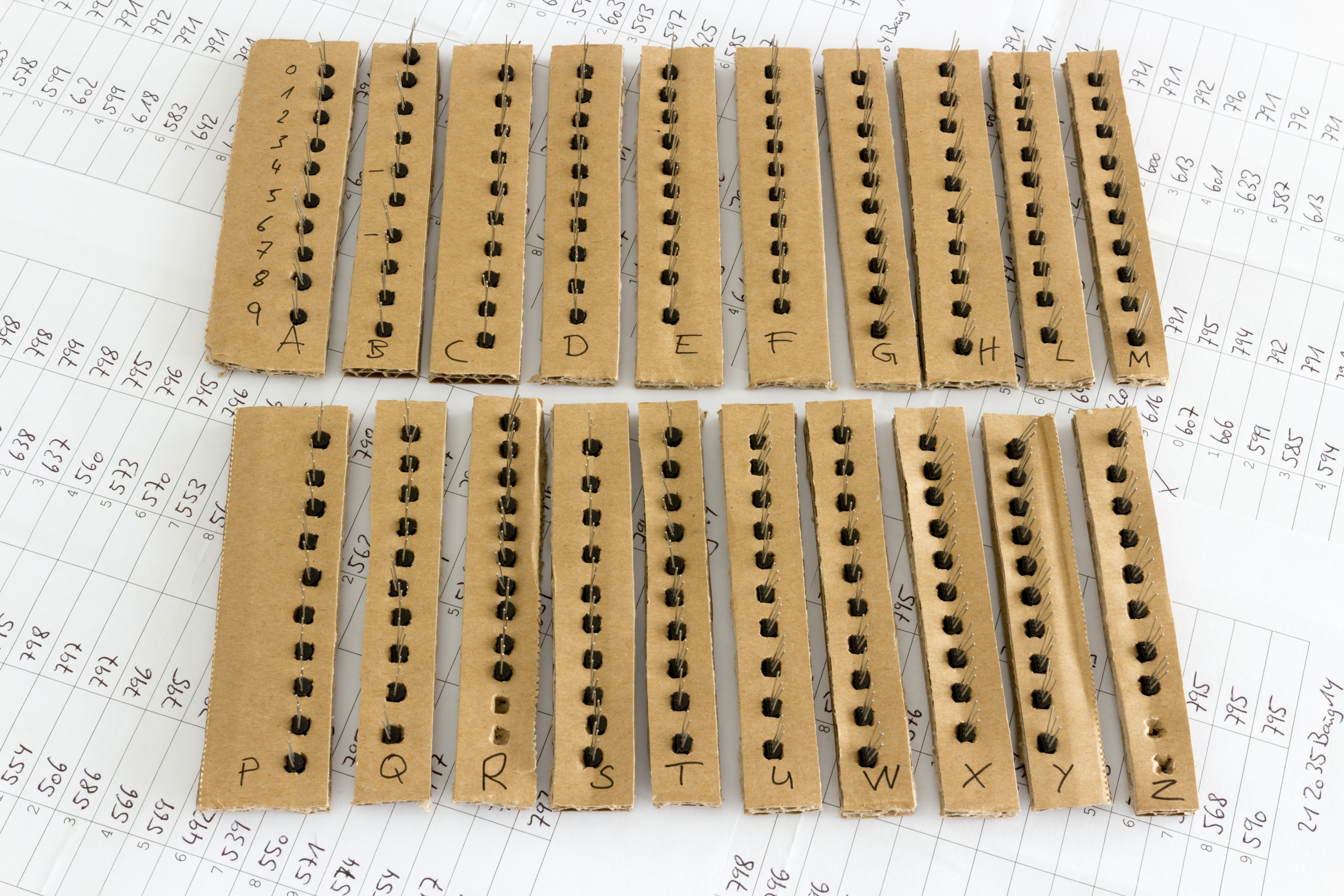
Cardboard strips for matching
For measuring each device I utilized a Atlas DCA75 Pro from Peak Electronic. I was content with the hFE the instrument put out. Tracing the curves for each device and comparing them to each other's seemed just too time consuming for me :) . To keep the parts separated and be able to number them, I 'invented' the use of cardboard strips with holes punched in them. One transistor in one hole and you’re set. This also helps to keep them at a constant temperature (at least that's what I hope) as you don't have to touch them when applying the test leads. The whole measurement procedure then took me around 90 minutes, having prepared the cardboard strips a couple of days before and letting them acclimatize.
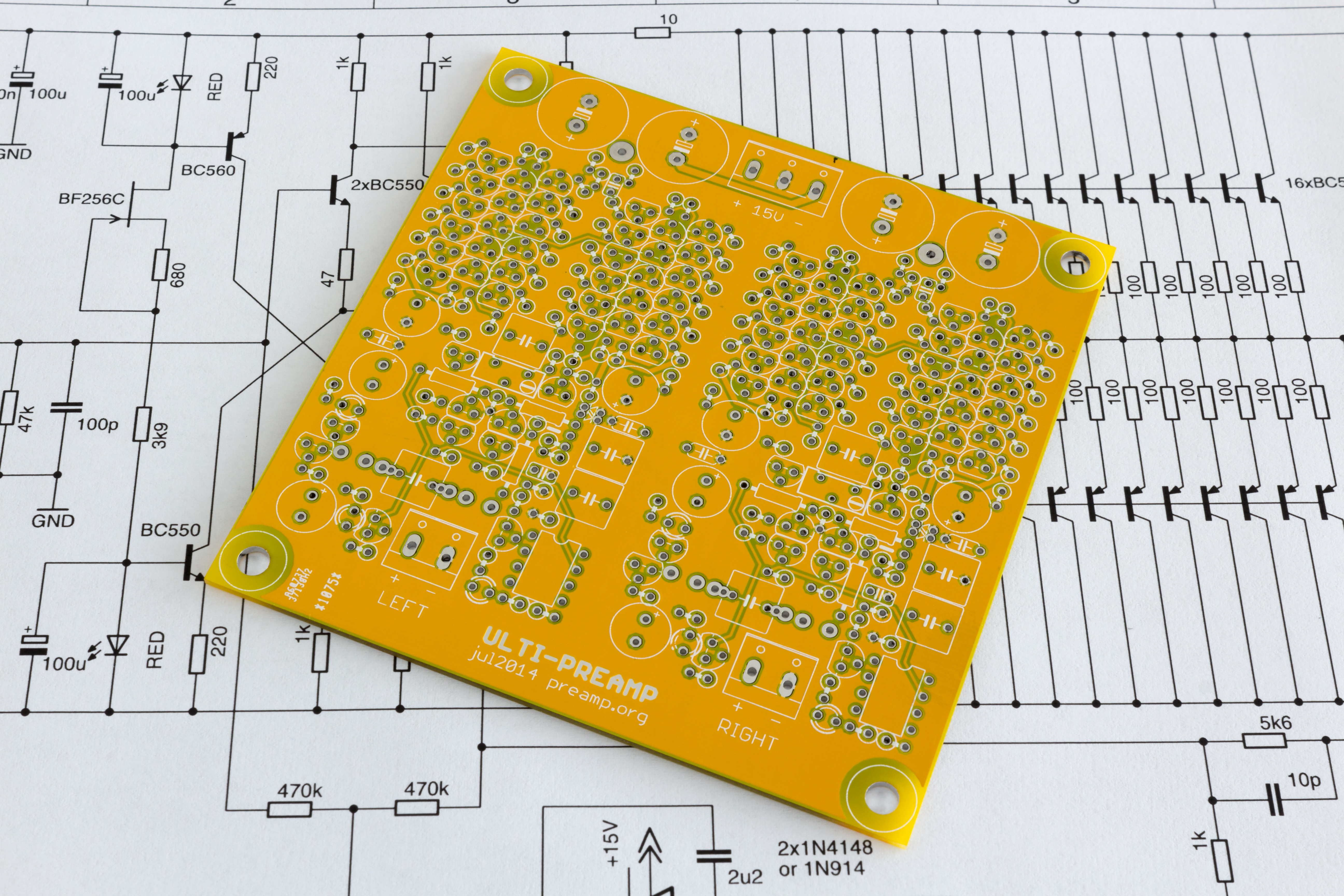
The first PCB showing the top layer...
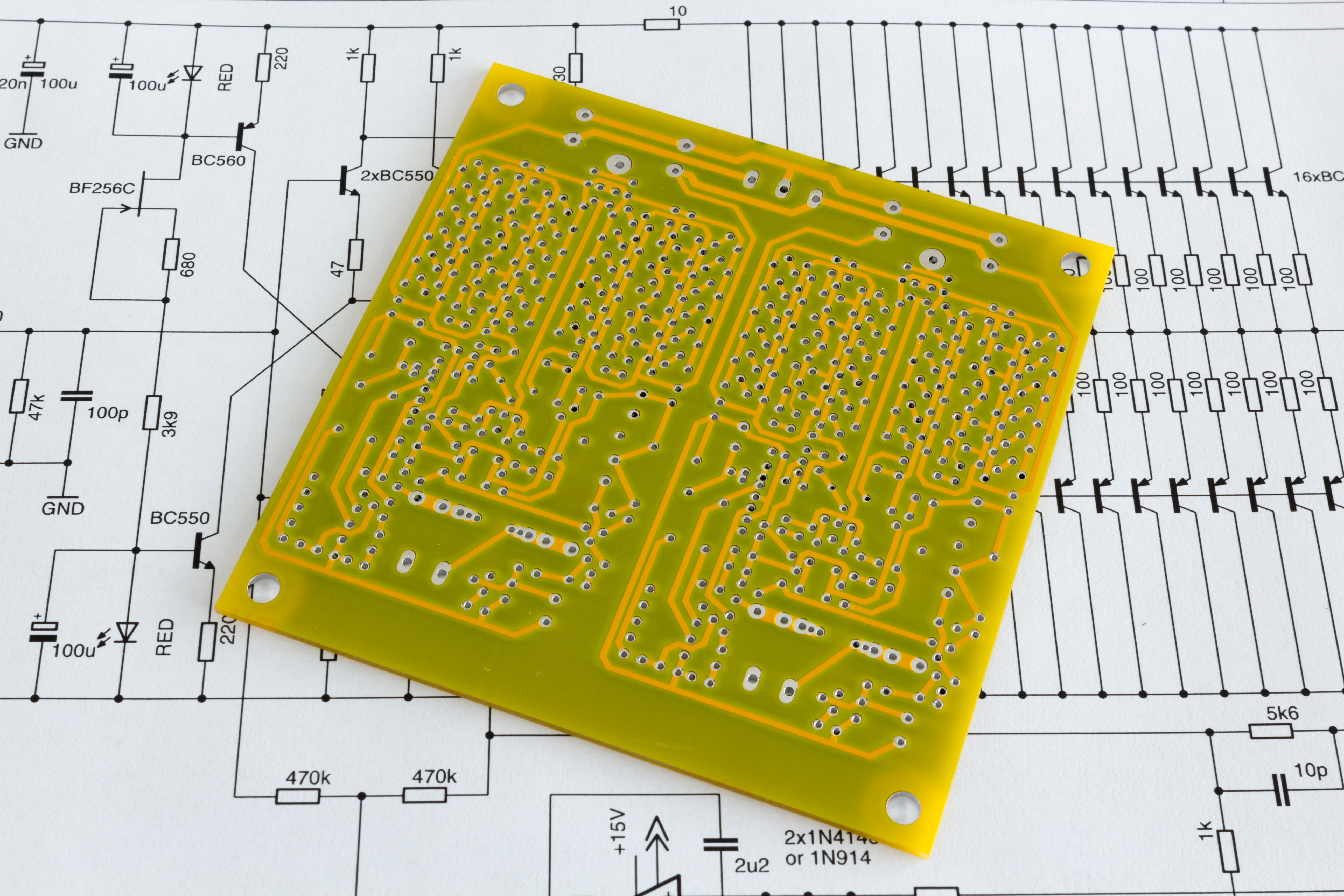
...and the bottom layer
Doing this thing on perfboard seemed impossible to me, so I created a nice double sided layout with a ground plane and send the boards to Dirt Cheap Dirty Boards. They look pretty nice and the price of $25 is unbeatable.
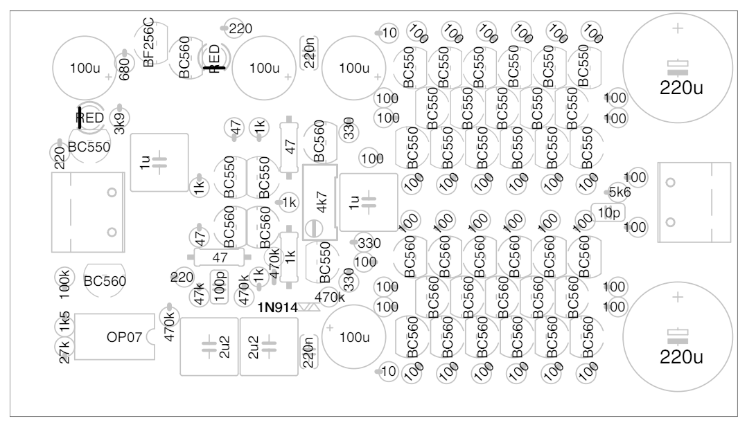
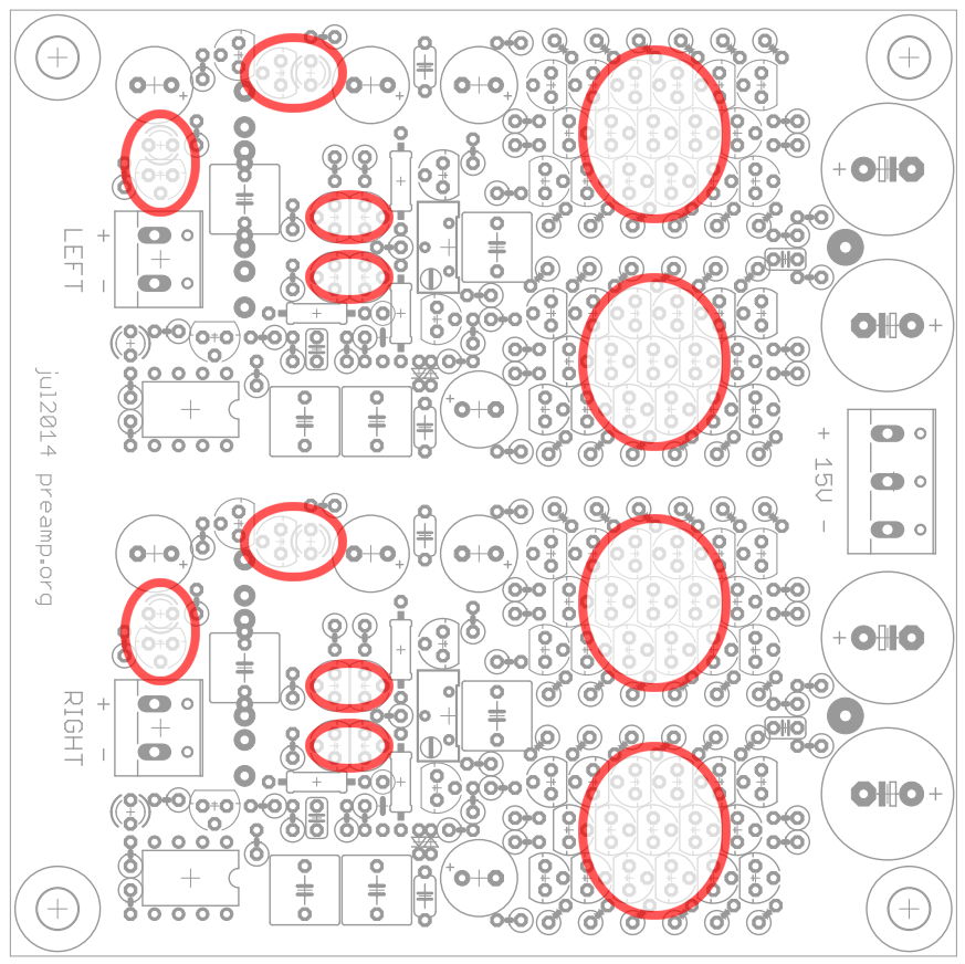
Component placement
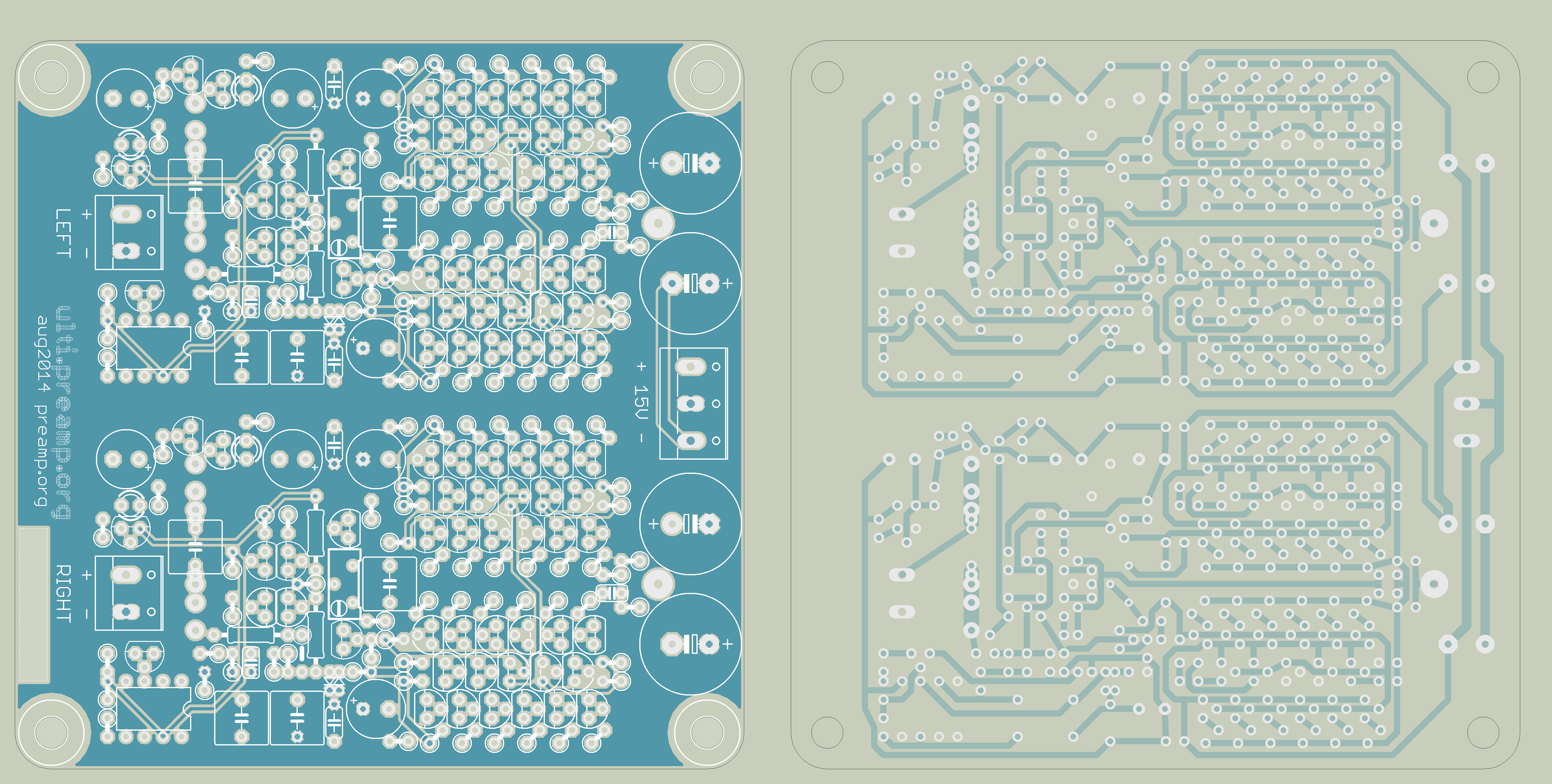
Layout
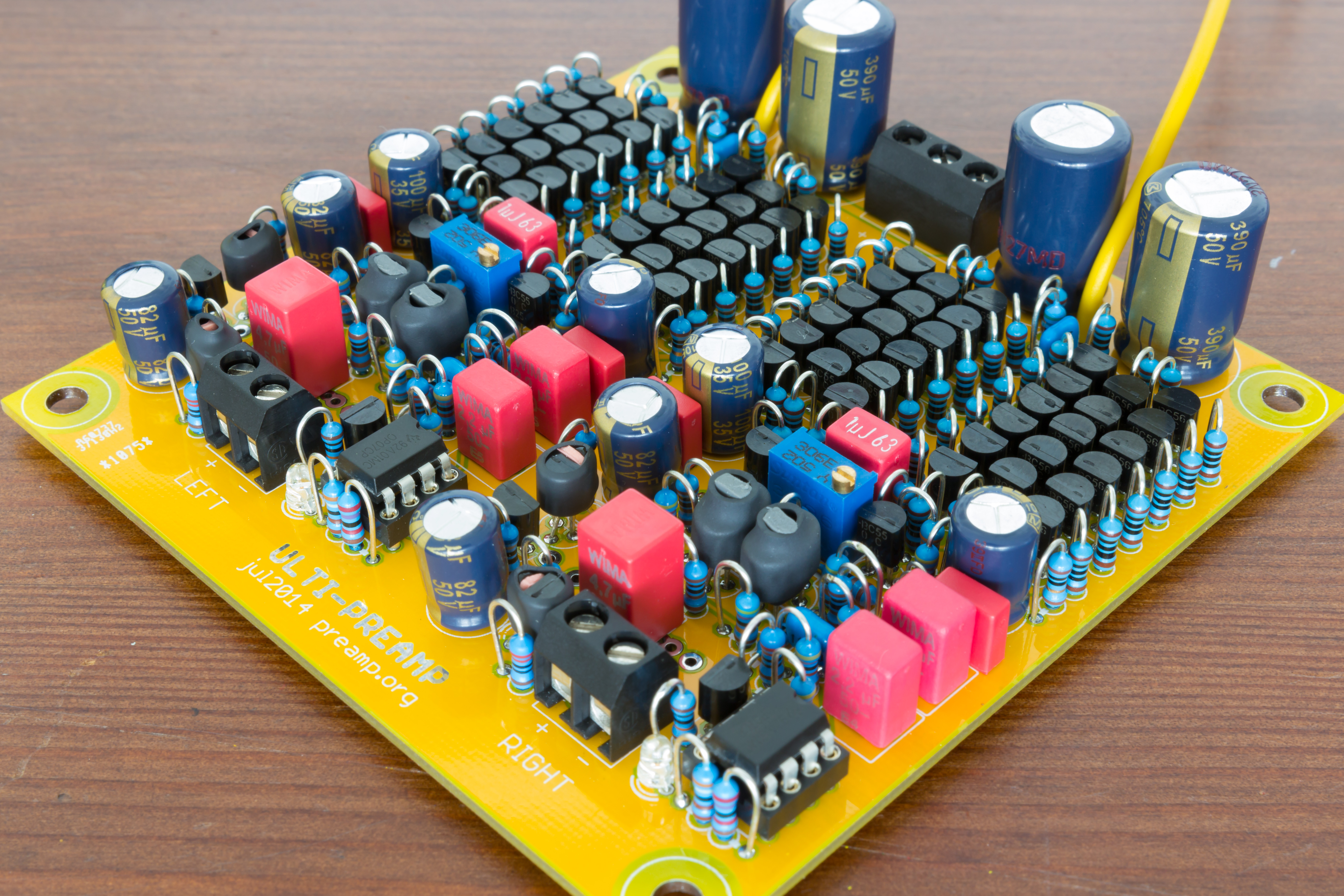
First prototype
again...
There're small thermal pads between the parts in the shrinking tube
Since I didn't build this thing yet, I can’t show you some real-world measurement results. You'll have to wait a couple of days for the missing parts to arrive and for me to finish :) . Meanwhile you can play around with the LTSpice sim file.
The first measurement!
I'm currently testing the amp's capabilities as a can amp. Using the cans as a load while performing a THD measurement turned out to be a bad thing, because there's a strong microphonic effect swamping everything below 1kHz. So here's a first measurement using SpectraPLUS and a 100R resistive load:
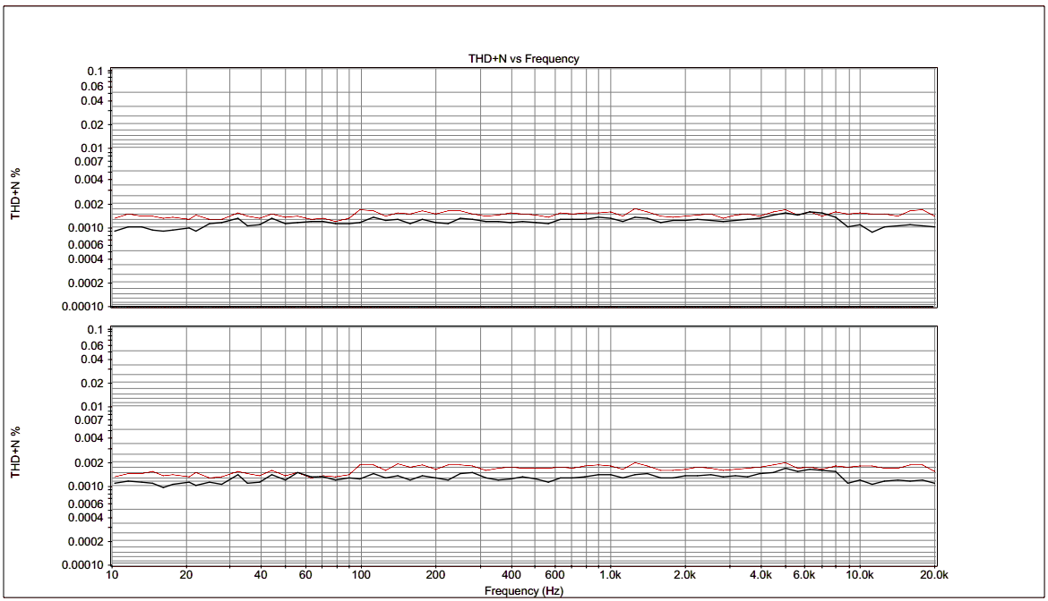
6.5dBu (1.636Vrms) at 100 Ohms
The black trace is the actual amplifier result, with its full gain and the soundcard output adjusted accordingly. The red trace shows a loopback measurement with the same soundcard settings. The cable alone picks up more noise than the amp! A single THD measurement at 1kHz showed 0.0003% for the loopback cable and 0.0008% for the amp, so everything is actually working fine. Now how do I get rid off that noise...
| ESI Juli@ set to -6dBFS. DUT output measured 6.570Vrms (16.35dBV or 9.291Vp) into 1kOhm (900+100 for 9:1 divider). Measured with ARTA | ||||
|---|---|---|---|---|
| Test / Bandwidth | 24kHz | 24kHz loopback | 96kHz | 96kHz loopback |
| THD 1kHz | 0.0016% | 0.00028% | 0.0028% | 0.0016% |
| THD 20kHz | – | – | 0.004% | 0.001% |
| IMD 4:1 60Hz+7kHz SMPTE | 0.0055% | 0.00094% | 0.0053% | 0.0016% |
| IMD 4:1 250Hz+8kHz SMPTE | 0.0064% | 0.0013% | 0.0059% | 0.0013% |
| IMD 1:1 13kHz+14kHz | 0.0013% | 0.00031% | 0.0025% | 0.00062% |
| TL074 at -6dBFS, loaded with 1k | ||||
| THD 1kHz | 0.00095% | 0.00028% | 0.0025% | 0.0016% |
| THD 20kHz | – | – | 0.014% | 0.001% |
| IMD 4:1 60Hz+7kHz SMPTE | 0.0065% | 0.00094% | 0.0069% | 0.0016% |
| IMD 4:1 250Hz+8kHz SMPTE | 0.0081% | 0.0013% | 0.0079% | 0.0013% |
| IMD 1:1 13kHz+14kHz | 0.0038% | 0.00031% | 0.0087% | 0.00062% |
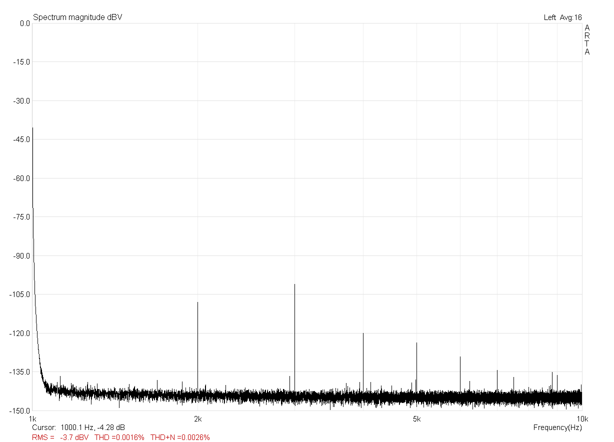
The spectrum at 1kHz and 24kHz bandwidth
TL074 Test Amp for reference
To make some reference measures, I created this little circuit. I used what was in the parts bin, which happened to be one of a whole lot of TL074' which I'll be using for a grid amp anytime soon :) . Of course this little guy here can't cope with the ulti-preamp in terms of current output, but that's no problem here for a 1k resistive load. I used the same psu and the same value feedback network, so that voltage output is comparable.
The measured values in the table above speak for themselves, and the plots below show the clipping behaviour of both circuits. Please note that I have made sure to clip the DUT only, and not the input of the soundcard used for measurements!
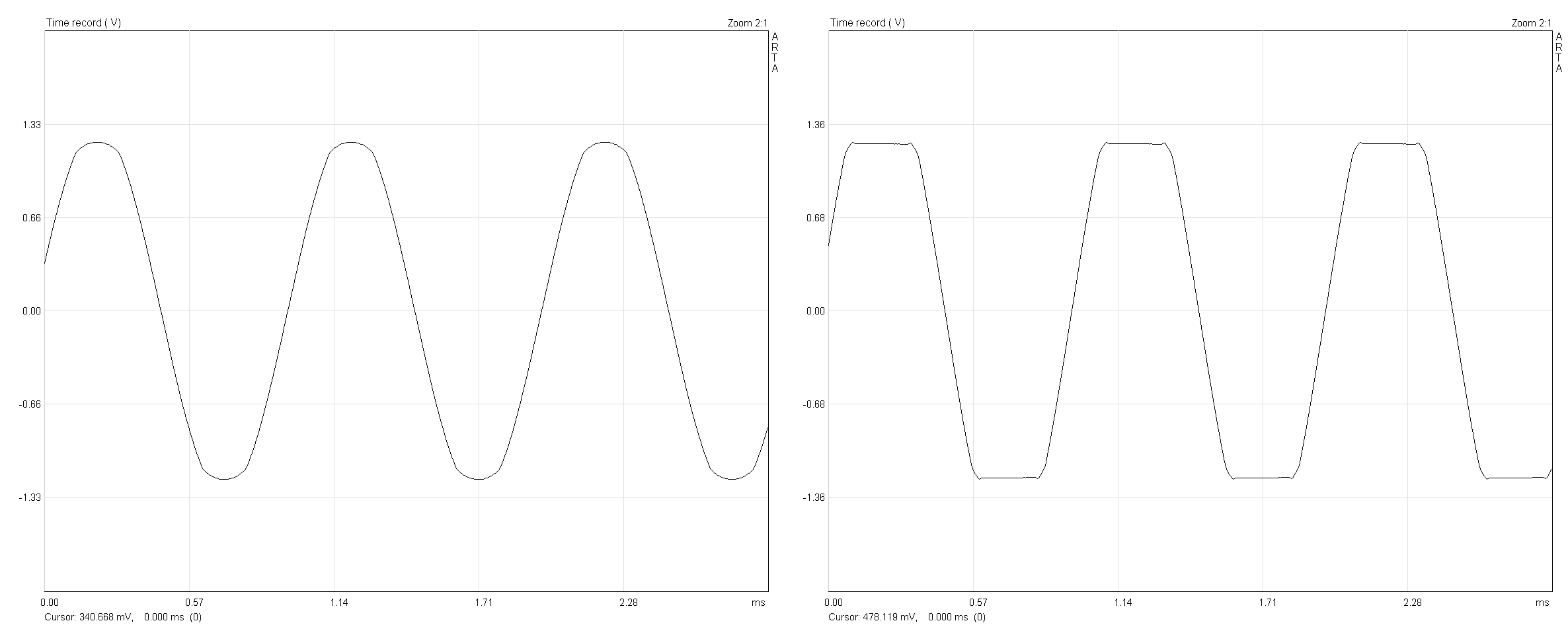
Ulti-Preamp clipping at -3dBFS and 0dBFS
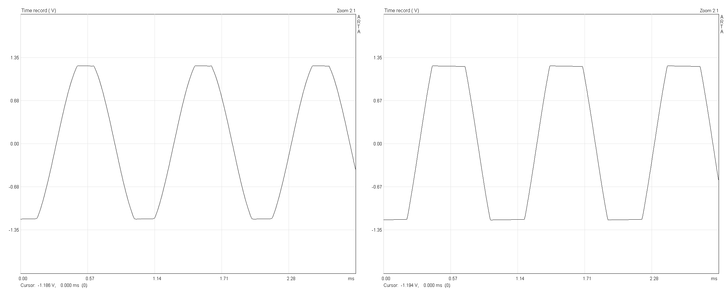
TL074 Test amp clipping at -3dBFS and 0dBFS