SSD1306 OLED 128x64 I2C current consumption
Out of curiosity I hooked up a small 0.96" OLED display to an amperemeter to measure its current draw. I was fiddling around with it, connected to the I2C bus of a Raspberry Pi, and wanted to get it up and running without using any of the existing libraries. Thus I had to send all the commands 'by hand' and stumbled over all the initialisation options mentioned in the datasheet of the driver chip. There are several voltages, frequencies and divider ratios to play around with, and I wondered how they would influence the power consumption of the display. After all, it might come in handy to know exactly what to do to trim the current draw to an absolute minimum, should this be necessary.
The hardware setup
I connected the pictured display directly to a Raspberry Pi, running off a standard 5V supply. Vcc to 3.3V (Pin 1 or 17), SDA to Pin 3, SCL to Pin 5 and GND to Pin 6 or 9 or any other ground pin. To make the multimeter readings a little more stable, I added a 100uF capacitor directly to the pins on the display.
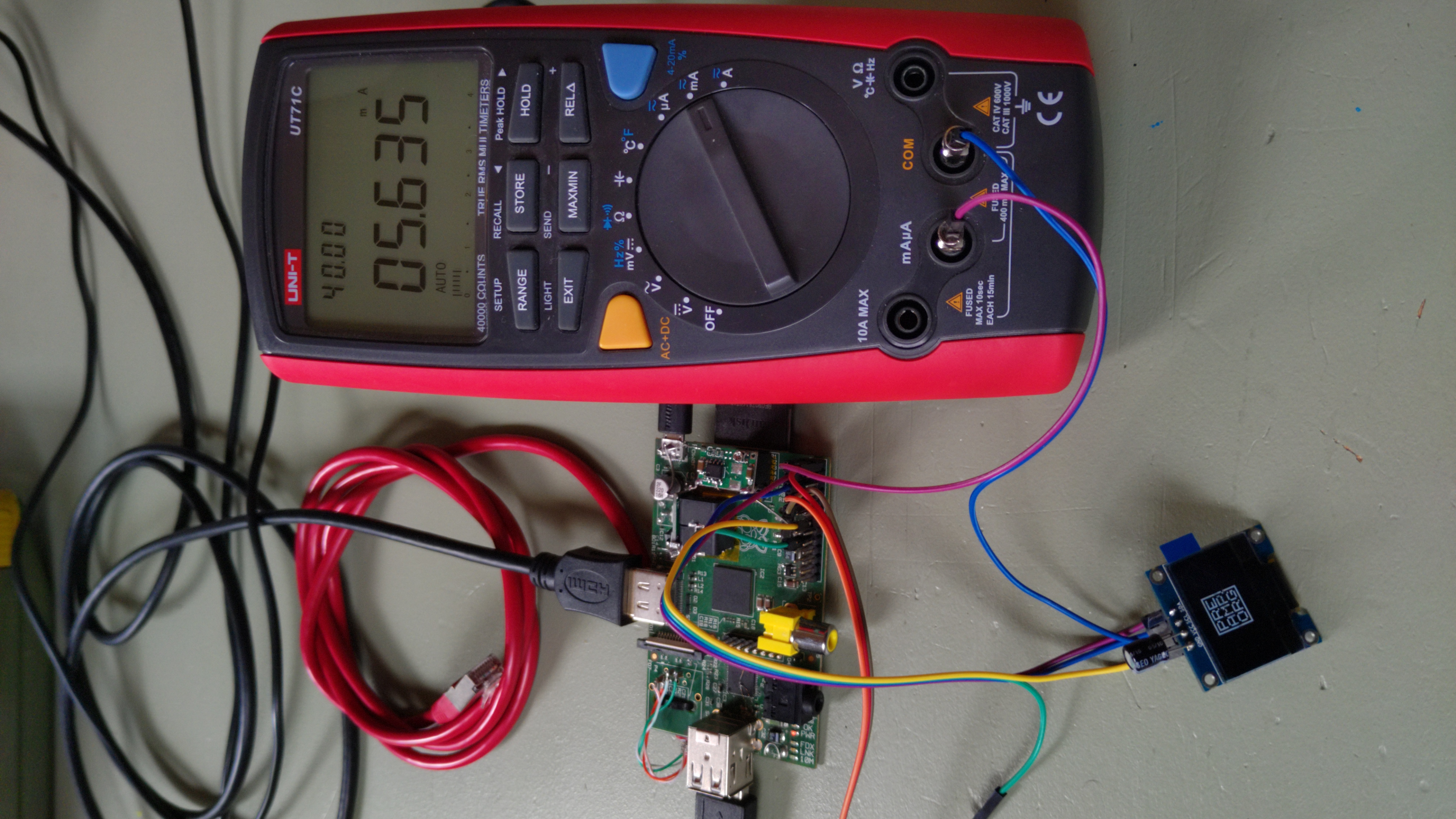
Display was set to maximum contrast and current draw, 13.65% pixels lit. Nevermind the other jumper wires. Picture taken with a Fairphone 4 (click for original file).
The initialisation
All the commands are sent using i2c-tools. The most basic initialisation is to enable the charge pump, set the correct orientation, horizontal mode, and then enable the display as such. Like this:
# basic initialisation
i2ctransfer -y 0 w9@0x3C 0x00 0xAE 0x8D 0x14 0xA1 0xC8 0x20 0x00 0xAF
Let me just walk you through this line. i2ctransfer is a command that lets us send multiple bytes to the I2C-bus at once, instead of the probably somewhat better known i2cset, which only sends a single byte at a time. That would work totally OK, too, albeit being terribly slow, once you start shoving loads of frames to your display.
-y tells it to be quiet and just send the bytes without asking for confirmation each time. That's pretty helpful if you send your commands to an EEPROM and may mess something up, but in this case we want speed rather than security :).
The following 0 is the actual I2C-bus number. Since you can have multiple buses on the Raspi, this might actually be a 1 or a 2 in your case. Use the following command to find out how many buses you have: i2cdetect -l.
w9@0x3C tells the tool to send 9 bytes to the bus address 0x3C. Instead of 0x3C in hex notation you could also use 60 in decimal, and obviously this address has to match that of your display. Use i2cdetect -y 0 in case you're not sure. Having to state the exact number of bytes is a little annoying at best, but pretty handy in case you want to clear the screen, for example. w1025@0x3C 0x40 0x00= will send one 0x40 to set the display in data mode, and then repeat the 0x00 (note the equal sign) for the remaining 1024 out of the total 1025 bytes to send. Try that with a loop of i2cset commands for comparison.
The remaining 8 bytes are the actual bytes that will be sent to the display. The first 0x00 denotes the command mode, so that the following 7 bytes will be understood as commands, and not display data.
Display something meaningful
This will get you started and probably show some random noise on the display. To clear the screen, we have to write all zeros to the whole RAM. Like I already mentioned, this is easily done like this:
# clear screen
i2ctransfer -y 0 w1025@0x3C 0x40 0=
To fill the whole screen, just send 255 or 0xFF instead of the 0: i2ctransfer -y 0 w1025@0x3C 0x40 0xFF=.
For 50% pixels lit we can either just fill the first half using i2ctransfer -y 0 w513@0x3C 0x40 0xFF=, or draw some line patterns like i2ctransfer -y 0 w1025@0x3C 0x40 0xAA= or i2ctransfer -y 0 w1025@0x3C 0x40 0xF0=.
We have two more ways to temporarily show a white screen with all the pixels lit. From a black screen, we can issue the following command to invert all the pixels at once:
# invert screen
i2ctransfer -y 0 w2@0x3C 0x00 0xA7
This is how to switch back to non-inverted display:
# normal screen, not inverted
i2ctransfer -y 0 w2@0x3C 0x00 0xA6
The other way is to set the entire display on, using the dedicated command 0xA5:
# entire display on
i2ctransfer -y 0 w2@0x3C 0x00 0xA5
And again switch back to normal display of the RAM content:
# normal RAM content display
i2ctransfer -y 0 w2@0x3C 0x00 0xA4
The settings to fiddle with
0x81: Contrast
The most obvious. Does just what it says and adjusts the current to the pixels in 256 steps. The range from darkest to brightest depends on the following parameters though. Reset value according to datasheet is 0x7F.
0xDB: VCOMH deselect level
If I understood the datasheet correctly, this is basically the 'off voltage' for the pixels, whereas the 'on voltage' is Vcc. Not so sure about this, though. What I observed is that a lower setting permits a much more dim display on the lower contrast settings, while leaving the brightest settings virtually unaffected, and thus increasing the total contrast range. Using the highest setting of 0x40 consequently renders the contrast setting almost useless. Reset value according to datasheet is 0x20, useful range is from 0x00 to 0x40.
0xD5: Oscillator frequency and clock divider
I simply call this setting 'clock'. It is conveniently composed of two nibbles with 16 values each. The first one sets the oscillator frequency (0x0_ for lowest, 0xF_ for highest frequency), while the second one sets the divider ratio (0x_0 for no divider and thus full speed, 0x_F for the highest divider). The clock setting has only minor influence on the actual screen brightness in some cases and mostly affects the refresh rate. The lowest oscillator setting shows some visual flicker, but can shave off one or two milliamps. My display emits some audible noise; the frequency setting can be used to tweak that noise into a not-so-annoying range if necessary.
The divider should always be left at 0, maybe 1 will be okay. All the higher settings show unbearable flicker with 64 multiplexed lines and are practically unusable. Try a setting of 0x0F (lowest frequency, highest divider ratio) and you can see the lines scan along the screen, with a refresh rate of something around 1 (yes, one). Reset value according to datasheet is 0x80.
0xD9: Pre-charge period
Like the clock setting, this one is also composed of two nibbles with 16 values each. The first one sets the discharge period (phase 1 in the datasheet), the second one the precharge period (phase 2 in the datasheet). If you don't allow enough time for the pixels to charge and discharge, they obviously won't achieve their full brightness, but this will save some power, on the other hand. Reset value according to datasheet is 0x22.
0xA8: Multiplex ratio
This will have to remain 0x3F to use the full display area with all 64 lines. Set this to 0x07 if you only want to use the first 8 lines, for example. This might be useful in case you need just one, but a really bright line. The clock speed will be 8 times as fast, and thus there's more current per frame for only 1/8th of the pixels. They won't magically be 8 times as bright, but the maximum brightness is a good bit more than that of the standard multiplex. Reset value according to datasheet is 0x3F.
Some results
Depending on how you initialized the display, it will draw between 0.4mA and 1.7mA even with a completely black screen. To properly send it into standby, and switch off the screen without losing RAM content, issue the command 0xAE. That will reduce the current consumption to a mere 15µA (yes, micro-amps), regardless of all the other settings. Use 0xAF to re-enable the display any time.
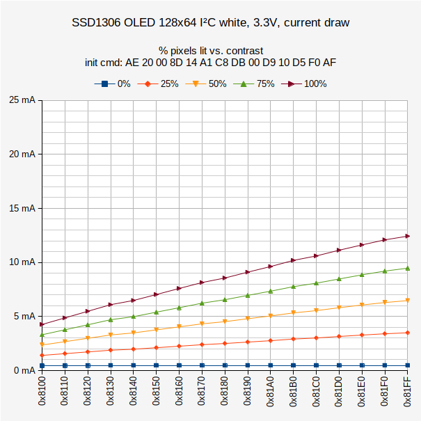
The following measurements were all done with all the pixels lit, to measure the highest possible current draw with the given settings.
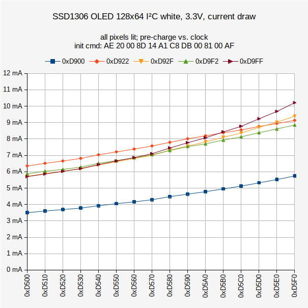
Five different pre-charge settings vs. clock setting on the X-axis. Lowest contrast and Vcomh, for lowest possible current draw.
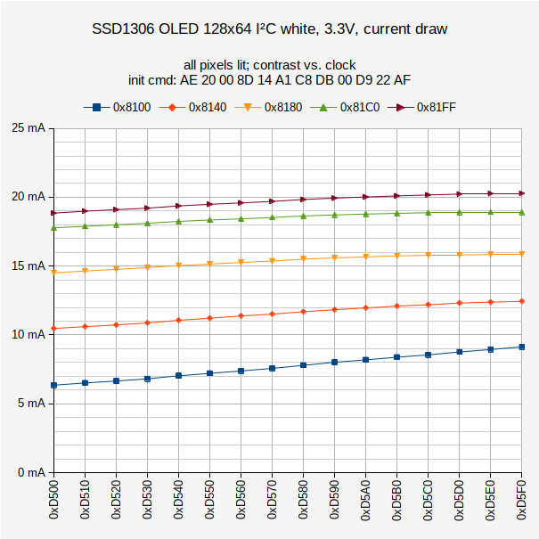
Five different contrast settings vs. clock setting on the X-axis. Lowest Vcomh and standard pre-charge. The oscillator frequency has a huge impact on visible screen flicker, but not that much on overall current draw.
Some more results
These are the settings that I deem the most interesting or useful. For an easy implementation, I have provided the complete initialisation in one line. Copy and modify them to your needs.
i2ctransfer -y 0 w15@0x3C 0x00 0xAE 0x20 0x00 0x8D 0x14 0xA1 0xC8 0xDB 0x00 0xD9 0x00 0xD5 0x00 0xAF
Lowest possible current draw while still retaining a useable image. Due to the lowest oscillator frequency you will notice some flickering. You might go even more extreme and start increasing the clock divider, but that would lead to really bad frame rates and unbearable flickering.
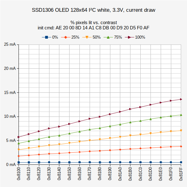
i2ctransfer -y 0 w15@0x3C 0x00 0xAE 0x20 0x00 0x8D 0x14 0xA1 0xC8 0xDB 0x00 0xD9 0x20 0xD5 0xF0 0xAF
Best contrast range. The lowest value will be very dim, while maintaining a good brightness close to maximum on the highest settings. Refresh rate as high as possible and thus no annoying flicker.
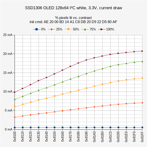
i2ctransfer -y 0 w15@0x3C 0x00 0xAE 0x20 0x00 0x8D 0x14 0xA1 0xC8 0xDB 0x20 0xD9 0x22 0xD5 0x80 0xAF
Standard values out of the box.
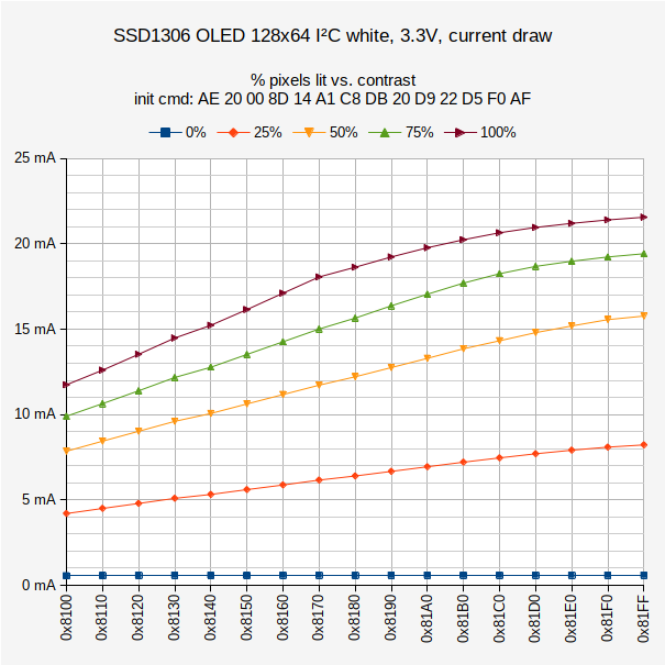
i2ctransfer -y 0 w15@0x3C 0x00 0xAE 0x20 0x00 0x8D 0x14 0xA1 0xC8 0xDB 0x20 0xD9 0x22 0xD5 0xF0 0xAF
Same as standard values, but with maximum oscillator frequency. Least visible flicker, but a little more current draw.
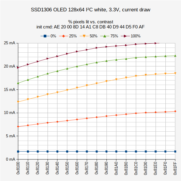
i2ctransfer -y 0 w15@0x3C 0x00 0xAE 0x20 0x00 0x8D 0x14 0xA1 0xC8 0xDB 0x40 0xD9 0x44 0xD5 0xF0 0xAF
Maximum possible current draw and brightness. Contrast range is minimal, there is only a subtle change in brightness between all the contrast settings. The highest recorded values that made it out of the graph are 25.05mA and 25.11mA, respectively.
i2ctransfer -y 0 w15@0x3C 0x00 0xAE 0x20 0x00 0x8D 0x14 0xA1 0xC8 0xDB 0x00 0xD9 0x10 0xD5 0xF0 0xAF
A very peculiar combination of the highest oscillator frequency and a certain discharge interval results in a lower gamma value, rendering the lowest ~40 contrast values invisible and thus useless.
Brightness comparison
Yeah, I totally have to take some pictures with uniform shutter speed for comparisons sake. Will do. Probably.
Update 2022-08-08
1.0 seconds, f/8.0, ISO 100, 70mm on APS-C (Sigma 70mm F2.8 DG MACRO | Art 018 on Canon EOS M 100)
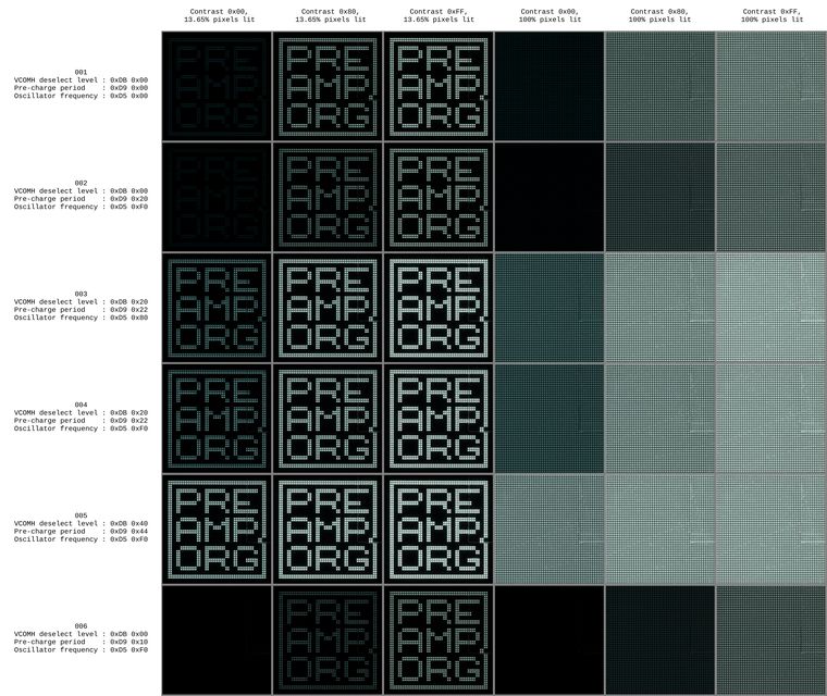
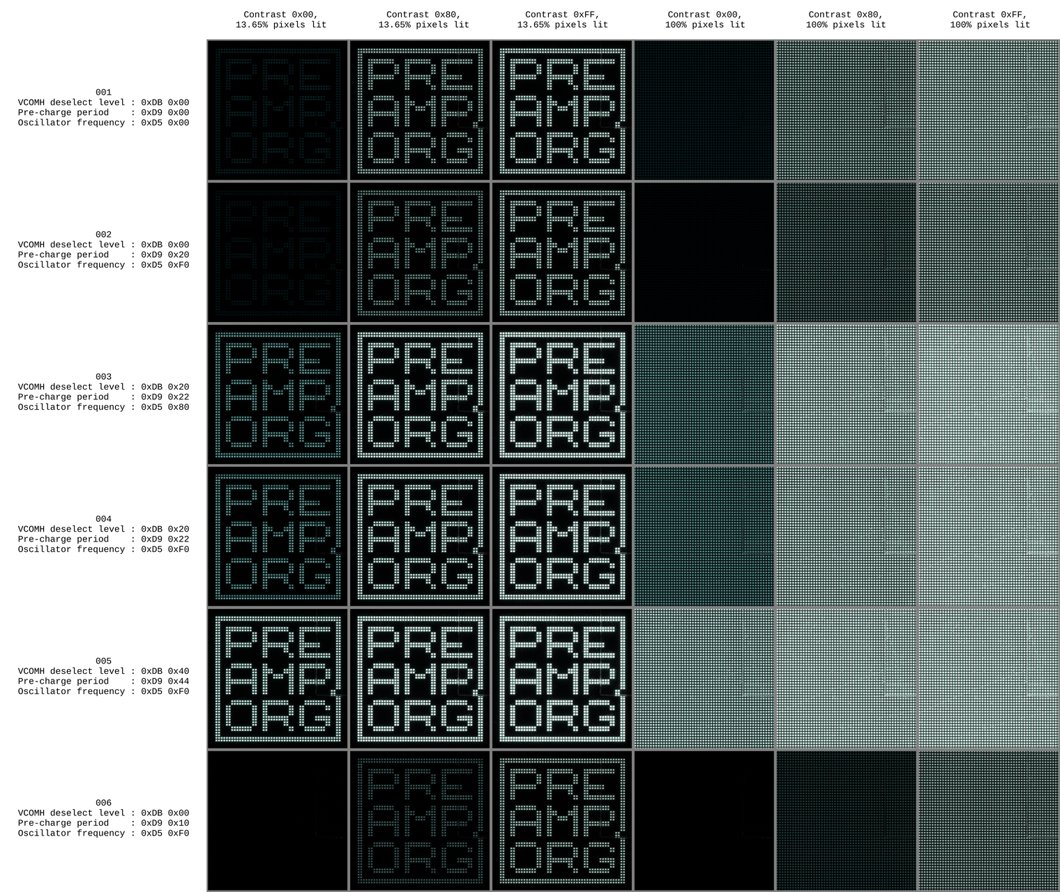
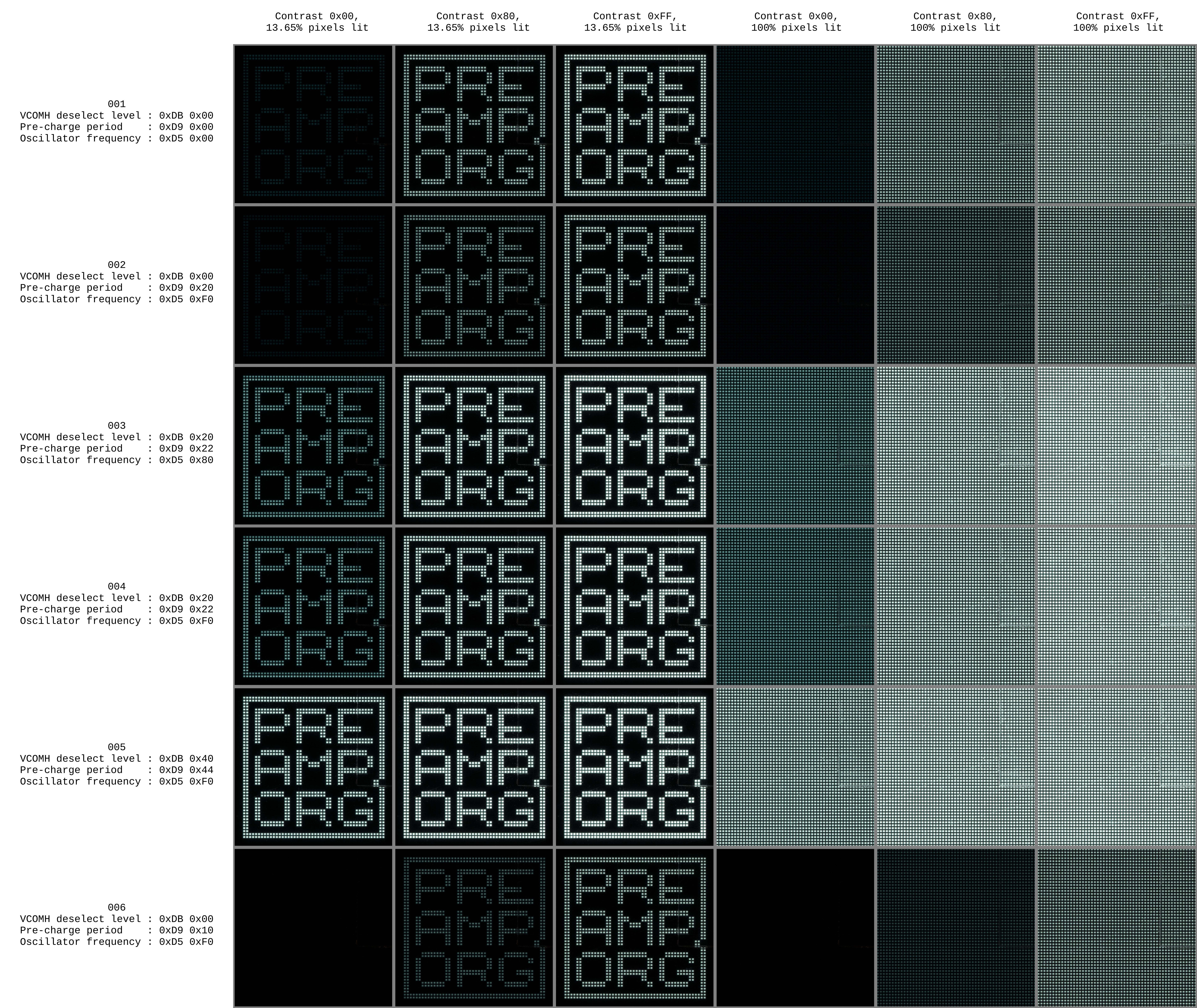
Here we go. Did a set of pictures with 0% - 50% - 100% contrast, respectively, displaying a) my logo and b) the full screen lit, like I did for the current measurements above. I chose a square crop for a less cluttered appearance. The six shootings, numbered 001 to 006, are in the same order as above, with the most important parameters added to the table. Feel free to download the full-res PNG version for your pixel peeping pleasure - it's 60 MB though, so maybe the slightly compressed JPEG version at 1/10th the size will do.
Note that on 0% contrast in setup 002 the pixels are actually still visible, while in number 006 they are completely off.
1520 x 1280 px, PNG, 2.96 MB
7600 x 6400 px, JPEG, 6.27 MB
7600 x 6400 px, PNG, 60.5 MB