Soldering station with TL494
I've actually been wanting to tackle this project for about ten years now. I never really had a need for it, so it always got postponed. Today I still don't have a need for it actually, but the time was about right and I took my chance.
What am I talking about? I wanted do build my own soldering station, of course, meeting the following goals:
- use a SMPS to do away with bulky transformers and with triacs and zero voltage switching
- be compatible to the soldering iron I already own, a Weller MLR-21
- an analog design with no microcontrollers on board
- use readily available parts, nothing special or unobtainium

The working prototype.
Since all the classic heater controllers of yore are pretty much gone by now (good luck finding your SL443A or U217B or T2117), I figured why not use a PWM controller for a switchmode power supply? SMPS' are ubiquitous today, after all that's one of the reasons for me to build this thing, and there are plenty controllers out there to choose from. Since I had already used one before, I decided to go with the TL494 again. That's a tried-and-tested methusalem, rugged, versatile, pretty much everywhere to be found, easy to work with, cheap, still in production, and probably still in production 20 years from now. Chances are great that you find one in the next PC power supply or car subwoofer amplifier that you pull out of the dumpster, and the TL is probably not the reason that the thing got trashed. Another great advantage is that this chip already has everything on board that we need for a soldering station, which keeps the parts count and complexity low.
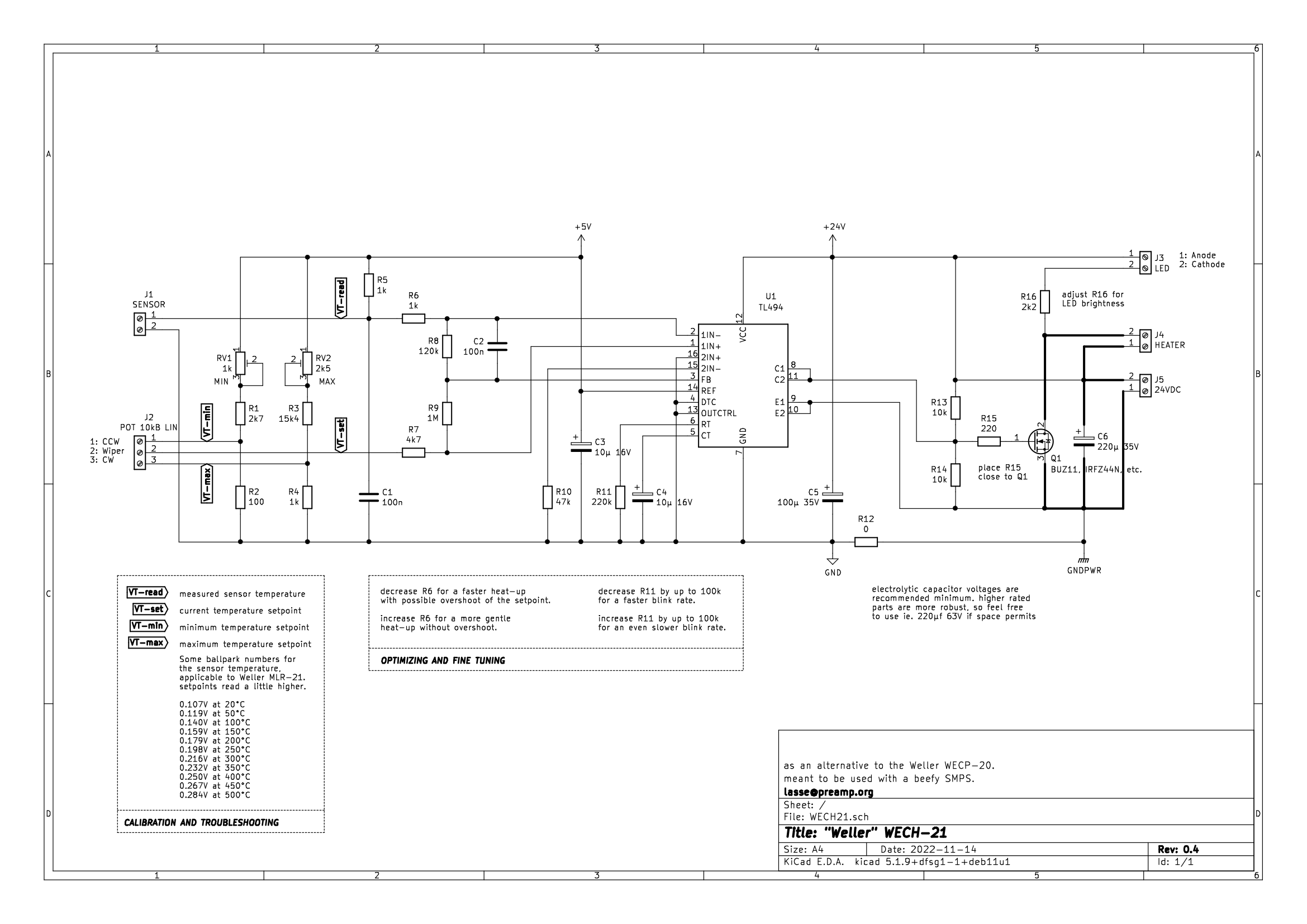
The schematic. Click on the image for a bigger version.
Click here for a PDF download.
Let me tell you some of the intricate details of this design. First of all, we don't use any external op amps and have no need for an additional negative supply rail. Everything is based on the 5V reference voltage supplied by the TL494, which can handle an additional 10mA. The TL runs happily from a 12V to 40V supply voltage, and we're comfortly in the middle of that range with no need to spend a second thought about pre-regulation.
The 494 has two op amps on board, with a common mode range including ground, pretty much like the classic LM358 and LM324. All four inputs are directly accessible, but the outputs are added together via diodes and only that common feedback point is accessible. This limits their use a little bit, but I got away using only one of them anyhow. Most of the soldering stations that I have looked at, are first amplifying the sensor signal to something like 5V for their maximum temperature, and then compare it to another voltage of equal magnitude that the user can dial in with a knob. Since that would have necessitated another op amp (with direct access to its output), I went the other way and simply compare a smaller control voltage to the lower output voltage of the sensor. In case of the Weller MLR-21, using a PT20 RTD supplied with about 5mA, we're talking about 100-250mV here. The op amps of the TL494 can easily deal with such low voltages at ground level, because that's not at all different from what they are designed to do, connected to a current shunt supplying only several millivolts. To make it possible to calibrate the min and max temperatures on the knob, I have added two adjustable reference voltages to the potentiometer. This has an advantage over the way it is done in the original Weller WECP-20, in that the settings are not interactive and thus don't affect each other. Well, they probably still do to some extent, but not as much as with other designs which set zero and gain. Here the gain stays fixed and we simply set a lower limit and an upper limit to compare the measured value to. Works like a charm and only needs one op amp. A possible downside might be that we are now dealing with (or dialing in) a rather low voltage, but I don't think that this will be a problem.
The switching duty is best left to a MOSFET, since we're now all DC and don't need a triac anymore. The exact type is not critical and you can basically pick what is left in the parts bin. It doesn't have to be blazingly fast, we're only switching about once per second, and the RDSon doesn't have to be specified in micro-ohms. You'd be hard pressed to find anything with more than a couple hundred milliohms anyway these days, as long as it isn't a 600V part. Pick anything with a VDS of 40-60V and it will be fine. You can even choose one in an isolated TO220F-package if you like, or a tiny SO-8 one for an SMD version. It won't need a heat sink and will stay cooler than your average triac. Since the switching demands are pretty low, I didn't go overboard with a fancy high-speed high-current driver circuit. The TL494 does have two driver transistors on board, but unfortunately they cannot be configured as a totem-pole. Which is no problem in our case here, really. So I simply used them both in parallel as an open collector with external pullup resistor. And a pulldown resistor. That pulldown would usually be somewhat higher in resistance to not interfere with the drive voltage, but this is exactly what I am intending here. It acts as a 50-50 voltage divider to drive the FET with 12V, as 24V would be a little too much for its gate and kill it. Simple and sufficient, no need for a Zener diode or anything.
C4 and R11 determine the oscillator clock frequency. Usually this would be somewhere around 70kHz, but with 10µF and 220kOhm we're just short of one tick every two seconds. This will make for a nice, slow and steady rhythm, just like the WECP-20 does with its SL443A. If you want to go even slower, try 270k or 330k instead. If you want to go faster, try 180k or even 120k. Of course you could just as well change C4, but I found 10µF to be a convenient and readily available value as an electrolytic. No need for a fancy red MKP here, although that would certainly work well.
If you had a thorough look at the schematic by now, you're probably asking yourself what R12 is there for. A resistor with zero ohms, why the hell...? Well, I tell you. It is only there to save you from totally fucking up your layout. After all we're dealing here with several tens of millivolts, right next to a MOSFET switching some amps at 24V, all referenced to the same ground. It might not be that big of a problem in this particular case, but this way you can easily keep the ''sensor ground'' and the ''switching ground'' separated, should you design your own circuit board. I only built a prototype on veroboard, but even there adhering to good layout practices is never wrong.
One more thing I should notice is the 3% minimum dead time of the TL494. That is usually needed to make sure that you don't kill your output stage if you drive it in push-pull configuration. In our case it is unnecessary, or even unwanted, if you're so inclined. After all it means that we can only turn on our heater for 97% of the time. Or rather only turn it off for 97% of the time, as that is the way that I configured it. This way the heater will actually heat up with 100%, which is probably just what we expect from it, but it won't fully turn off in case you dial in a lower temperature. In fact it will be turned on for about 50 milliseconds every 1.8 seconds. This won't be a problem in actual use, but you may notice the LED flickering anyhow. Which might as well be a feature, indicating that the station is still alive ;).
Should you want to fiddle with the ballistics to optimize them to your liking or your particular soldering iron, maybe because the station tends to overshoot the temperature setpoint, or approaches it too carefully and you want more speed, then resistors R6 and R8 are the ones to look at. They set the gain for the sensor; more gain means a steeper slope and thus a more ''aggressive'' behaviour. Decrease R6 or increase R8 to make the control loop faster and probably overshoot, or vice versa to ease it a bit if it is already overshooting. R9 adds a little negative feedback to the temperature target setpoint (actually it adds positive feedback, which gets reduced the closer the setpoint is to the measured temperature, so it acts like an overall negative feedback). Reduce R9 to increase this negative feedback effect, or leave it out altogether for no feedback at all. The value of R9 depends on those of R8 and that of the 10k pot. I have tried to optimize this as good as I can, doing several measurement runs with different values, and from what I've observed from my prototype build, it looks pretty damn good! I won't claim it to be perfect though, so feel free to tweak the values to your hearts content.
Downloads