LTspice-shenanigans
These are just some collected tricks and helpful stuff to copy and paste and/or use as needed. Mostly for myself, so don't complain that I am missing this or that. Although I may add it here, in case I like it.
A more convenient symbol for the TL431 model
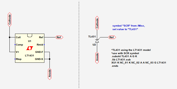
LTspice does not have a dedicated TL431 model. It does however have a model for the LT1431, which will be functionally identical to a standard TL431 most of the time. Here is one way to use the somewhat more familiar looking SCR symbol instead and reduce some of the visual clutter.
Press ''S'' to enter a new spice directive and paste the following text there:
*TL431 using the LT1431 model
*use with SCR symbol
.subckt TL431 A G K
.lib LT1431.sub
XU1 K NC_01 K NC_02 A A NC_03 G LT1431
.ends
Now press ''F2'' to add a component and select [Misc] SCR. Change its value to ''TL431'' and you're good to go. The LT1431 model as well as the SCR symbol are integral part of LTspice, so no external dependencies here.
Potentiometer or adjustable resistor
Connect two resistors in series and assign them the values {ra} and {rb}, respectively. Note the curly braces and don't omit them. Press ''S'' to enter a new spice directive and paste the following text there:
.param rt=5k
.param ra=rt*rp+1m
.param rb=rt-ra+1m
.param rp=0.5
Change rt to the value of your pot, 5k in this case. Vary rp from 0 to 1 to set the wiper position. You can use the .step command to make several simulation runs with different wiper settings, like .step param rp 0 1 0.1: that will yield 11 runs with 10%-steps from 0 to 1, ie. one full turn from left to right.
Plot resistance values
This may come in handy for arbitrary voltage sources or things like Zener diodes. Hold down the ''ALT'' key and left-click on the part you're interested in. That will add a plot for the device power (you already knew that one, right?) with a title like V(N010,ac)*I(D1). Now right-click on that title in the waveform viewer and change the asterisk into a slash, so that the expression reads V(N010,ac)/I(D1). The scale will change from watts to ohms and there you are.
Simulate a RTD in the time domain
Sometimes you may wish to simulate a nonlinear resistance in you transient analysis, according to some special behaviour. Let's say we're simulating a soldering station and we want to see what the controller does when the temperature varies several degrees around the setpoint. Would be nice if we could just set up a SINE or PULSE stimulus like we can do for voltages, but vary a resistance value instead, according to some magical arcane formula. So let's do this. Add a voltage source first and set it up to your liking. One volt will be one kelvin of temperature change. Press ''G'' and place a ground symbol to the negative pin; press ''F4'', enter pt, and place that label on the positive pin. You can actually call it what you want, but you'll have to accommodate for that in the following formula. We need some additional parameters for that, so add the following text as a spice directive (press ''S''):
.param pta=3.9083e-3
.param ptb=-5.775e-7
.param ptr0=100
As you may have guessed, we're designing a platinum temperature sensor here, like it is used by manufacturers like Weller. The parameter ptr0 sets the base value of the sensor at 0°C. You can easily adapt that to the common values of PT100 or PT1000. Bear in mind though that I have simplified the formula a little and left out the third term, which makes this model only accurate for temperatures above the freezing point! Finally, add a resistance and assign it the following value:
R=ptr0*(1+(pta*v(pt))+(ptb*v(pt)**2))
The term v(pt) resembles our voltage value and is thus the proxy for our changing temperature value. Of course this works with fixed DC voltages or stepped sources, as well as with any other voltage node, like the output of an op amp.
Better results for THD simulations
Just a short recap from an older article I wrote.
Press ''S'' to enter a new spice directive and paste the following text:
.opt plotwinsize=0
.opt numdgt=7
.opt method=gear
.opt maxstep={2**-20}
This will disable waveform compression and increase the numerical resolution, which helps tremendously when dealing with results in the range of 0.0000-something.
(more stuff to follow)