8-channel DS18B20 temperature logger with AVR and UART
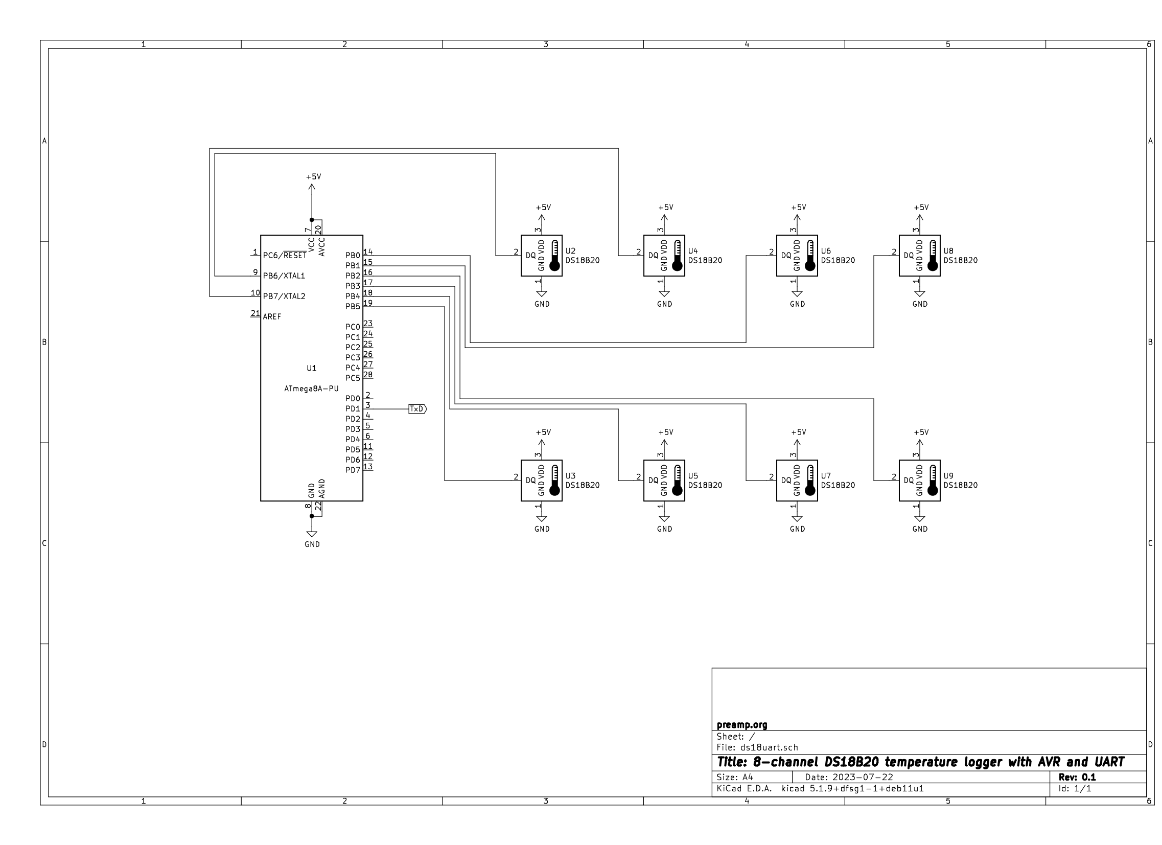
almost no need for a schematic...
So here's the problem: Say you want to log some temperatures over the course of several hours, or even days at a time. You'll need something to store all those data to; a Raspberry Pi or an old laptop will do the trick. A single temperature probe won't cut it though, because you're interested in several spots and the temperature difference between them. Whipping up a single analog sensor and the accompanying AD converter may be feasible, but doing that multiple times will get long in the tooth pretty soon, since you'll have to calibrate each one somehow. The next best option is, of course, the now ubiquitous DS18B20 from Dallas/Maxim/Analog (whatever): It is cheap, reasonably precise and accurate, calibrated right out of the box, and you can easily put a bunch of them on a single 1-wire bus. In case you're looking for something even more precise (and more accurate, too, as long as you can calibrate it that well yourself), I can highly recommend you the work of Ed Mallon over at The Cave Pearl Project!
I started out tinkering with half a dozen of those DS18B20s and hooked them up to a single GPIO pin of a Raspberry Pi. The Raspi has some libraries available to directly support a 1-wire bus on one of its GPIOs. Unfortunately I had to find out that the library I tried is somewhat limited. It basically just lets you read a single temperature value with the highest 12bit resolution of a single sensor at a time, as soon as you acquired its serial number and addressed it directly (so not exactly plug-and-play). To be fair, this is probably enough for 99% of the things that people want to do. With an 8bit resolution you're only precise to 0.5 degrees Celsius, but the readout would become a lot faster compared to the standard 0.75s. Anyway, I am fine with the 12bit mode, but talking about 'faster': How do you manage to read six sensors at once, every second? I googled a lot, but didn't find a lot of answers :(. Simply reading the sensors in succession is no good, because you'll always be a couple of seconds out of sync from the first to the last sensor, and your sample rate effectively decreases to 1/n. A workaround that I used was to start all the conversions as separate processes in close succession (which is as good as instantly) and let them write their results into a file as soon as they were finished. Then I could read all the results from those files (for which I put up a small ramdisk with tmpfs) and keep up a sample rate of about 1.5 seconds.
That worked okay actually, but there's another potential problem with this approach. I had connected all the sensors with 20cm jumper wires each to a small strip of veroboard, which in turn was hooked up to the Raspi over a 5m headphone cable (three conductors, small connector, what's not to like?). A star connection, basically, on an extension cord. According to the datasheets for 1-wire though, you're supposed to daisy-chain your sensors along the cable, not unlike a string of fairy lights. Since all the sensors are connected to a single data line, they have to deal with a race condition when the master wants to talk to them. Having a couple of meters of wire between each sensor is of tremendous help here, since with a star connection (of equal length) they are basically all the same distance to the master. In practice this is not necessarily a problem, but keep it in mind if your sensor network seems to act up under special occasions. Apart from that, a daisy chain of temperature sensors was not exactly what I wanted, so I had to figure out another way.
My idea thus was to use an AVR microcontroller as a ''multi master'' for several 1-wire busses with only a single sensor connected to each, and then send all the collected temperature values via serial UART to a computer. I think there are chips out there that can basically do exactly that, but since 1-wire is rather easy to bit-bang, I preferred the DIY way and not having to deal with some probably niche and hard-to-get components.
This approach actually has some really nice benefits:
- All temperature conversions are started at exactly the same clock cycle.
- Each of the up to eight sensors can be connected with its own length and type of cable.
- The sensors can be connected and disconnected on the fly and are interchangeable.
- No need to specify any serial numbers!
- Due to polling of the busy flag the sample rate can be as fast as possible and doesn't have to be fixed at 1/750ms.
- All eight temperatures are transferred at once as hex values in a single comma separated line, which can easily be read and logged on any computer with a terminal program like PuTTY.
How it works
I picked the good old ATmega8(A) for this purpose, but any other AVR should work as well. If it has an UART on board that's nice, otherwise the TX routine has to be bit-banged as well. Make sure though that it has a fully equipped Port left in case you need all the 8 channels. A tiny85 should do it for four. The CPU is clocked from the 1MHz internal RC oscillator, so no need for an external crystal. Max reliably achievable UART speed is 4800 baud, which is plenty fast enough, since we have the whole conversion time of >600ms without slowing anything down. The whole program runs in a constant loop, without any sleeps or interrupts. Exact timing is achieved by carefully interspersed NOPs and incorporating the 4 cycles for RCALL and RET into the timing budget. The first transmitted line after power-up will actually contain garbage, since there was no preceding temperature conversion to fill the buffer. The sequence is as follows: After initializing the necessary requisites like UART, stack pointer and port pins, the main loop begins with an 1-wire reset command. That command is applied to the whole port (PortB in this case), and thus to each of the eight port pins individually and at once. After that the skip rom command (0xCC) is sent, to avoid addressing each sensor by its 64bit serial number. Since there is only just one sensor connected to each pin (equal to a separate bus), this works a treat and much faster. Next up follows the convert temperature command (0x44) to start the conversion. From now on we have a couple hundred milliseconds of time to prepare the UART transfer while the sensors are busy doing their conversions.
And we do need some time here. Due to the nature of the 1-wire protocol, we're always reading one bit at a time. In this case though, we're reading eight one-bit's at once, which are more or less conveniently stored in a single byte. I did not bother to utilise the SRAM in this case, because there are enough registers there to do the job (R0 to R15 in this case). The first byte now contains the first bits of each of the eight sensors. After reading in the first eight data bits (sic!), we now have eight bytes of temperature data spread across eight registers in memory. Think of it as a table with 8 rows and 8 columns. One byte equals one row, but our data is arranged in columns. We have to pivot (or transpose) the table first, to get the eight bits of each sensor into a corresponding byte. I am not sure whether the code I have come up with is the most elegant way to do this, but it certainly does the trick within the constraints of CPU time and program memory. It just shifts each of the 8 bytes to the right (ASR), popping one bit into the carry flag, and then rotates that flag into a new buffer (ROR). That way exactly one byte (comprised of one bit of each register byte) ends up in the new buffer byte, lined up in the correct order. This process is repeated another seven times, until each register was shifted 8 times (and is now empty), and 8 new buffers are filled. Then I copy those new buffers (called ''buf0'' to ''buf7'') back into the old and empty registers (R0 to R7) to save them for later, because now I need the new buffers again for the second temperature data byte(s). They end up in the registers R8 to R15 and have to endure the same procedure.
Now that the data is in correct order, it's time to convert it into human-readable and terminal-friendly hex codes. Then each hex letter is sent out one by one, each word of four signs separated by a comma, and finally the whole line terminated by a CRLF, or /r/n if you prefer.
All this data juggling and sending takes around 90ms, so according to the datasheet we have another 660ms time to waste until we can proceed with reading in a new set of temperature values. Of course I have set up a wait loop to do exactly this. But I have implemented another feature. If the sensor is busy converting the temperature data, and you issue a read command (the same that is used to read a single bit), it will answer with a zero if it is busy, and with a one (equal to an empty bus with pullup) if it is done. I have simply incorporated this poll into the wait loop, where it is executed around every 20ms. And it is applied to all eight sensors, of course. By simply reading in the whole port and checking for all the bits to be ones, I can be sure that all the sensors have finished their conversions and can now jump out of the wait loop! Worst case, if one port pin gets continually shorted to ground, you'll have to wait the whole 750ms each time, but the loop certainly won't halt. With my test sensor connected, one conversion cycle took 621ms and was thus about 20% faster than the recommended maximum. Of course this time will vary with the conditions the sensor is in, but it will always be as fast as possible, give or take 20ms.
After the conversions are all done, we can now read the fresh data from the scratchpads. To do this, we have to repeat the reset command and the skip rom command (0xCC). It seems a bit strange to issue a reset before reading the data, but this is the only way to go. Sending the read pad command (0xBE) directly after the conversion is complete won't work, as the sensor won't answer. Now we have to send 16 commands, each one to retrieve a single bit. Thankfully the most interesting data (the actual temperature value) is contained in the first two bytes of the 9 byte long scratchpad, and it is sufficient to read in only those two bytes and then continue with a reset. We could go on and read the rest, calculate a checksum, and compare that to the checksum contained in the very last byte, but, naah :).
Here are some screenshots from the logic analyzer, showing how that whole procedure looks like on a time base.
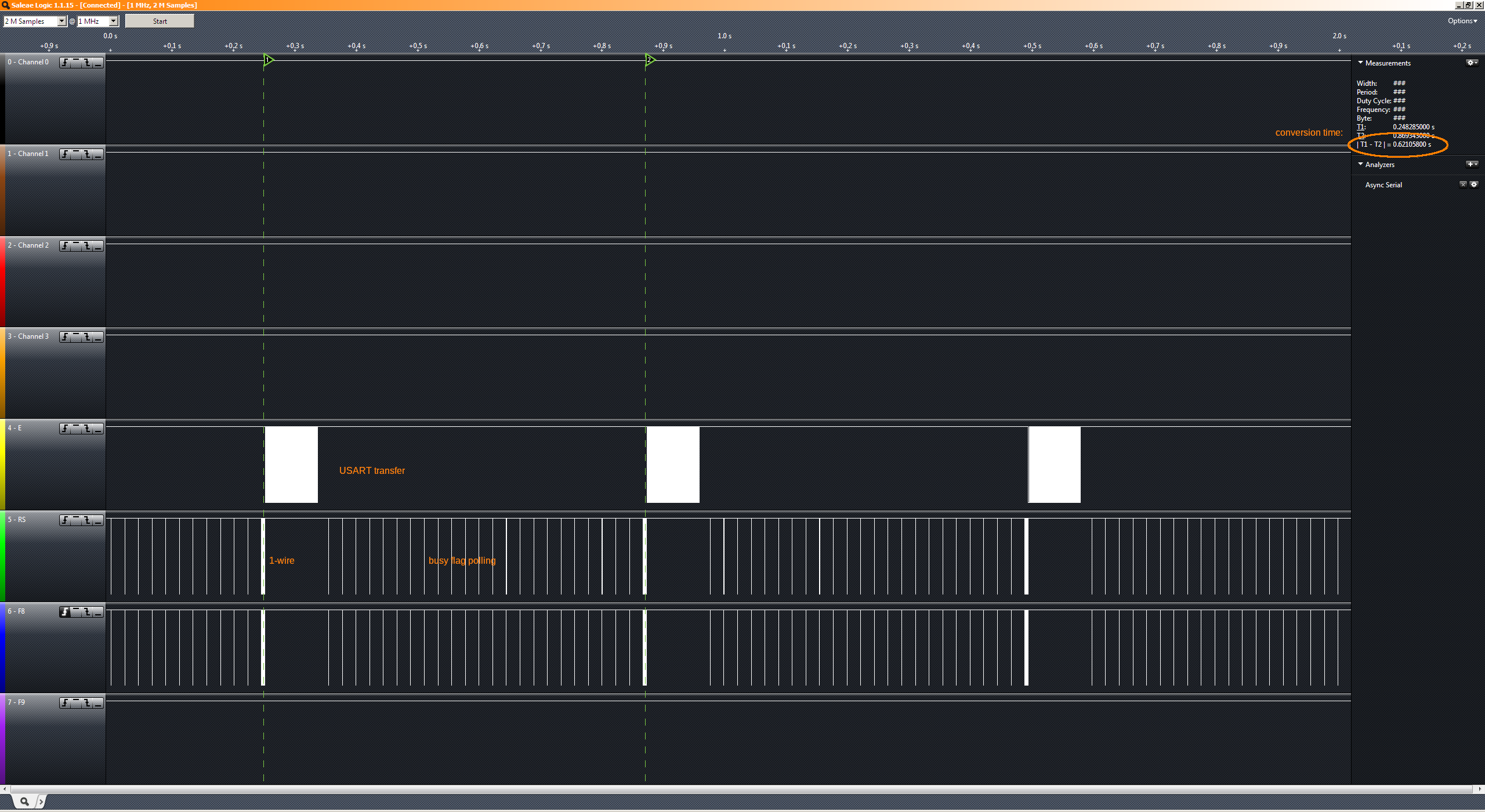
Three conversion cycles as a whole.
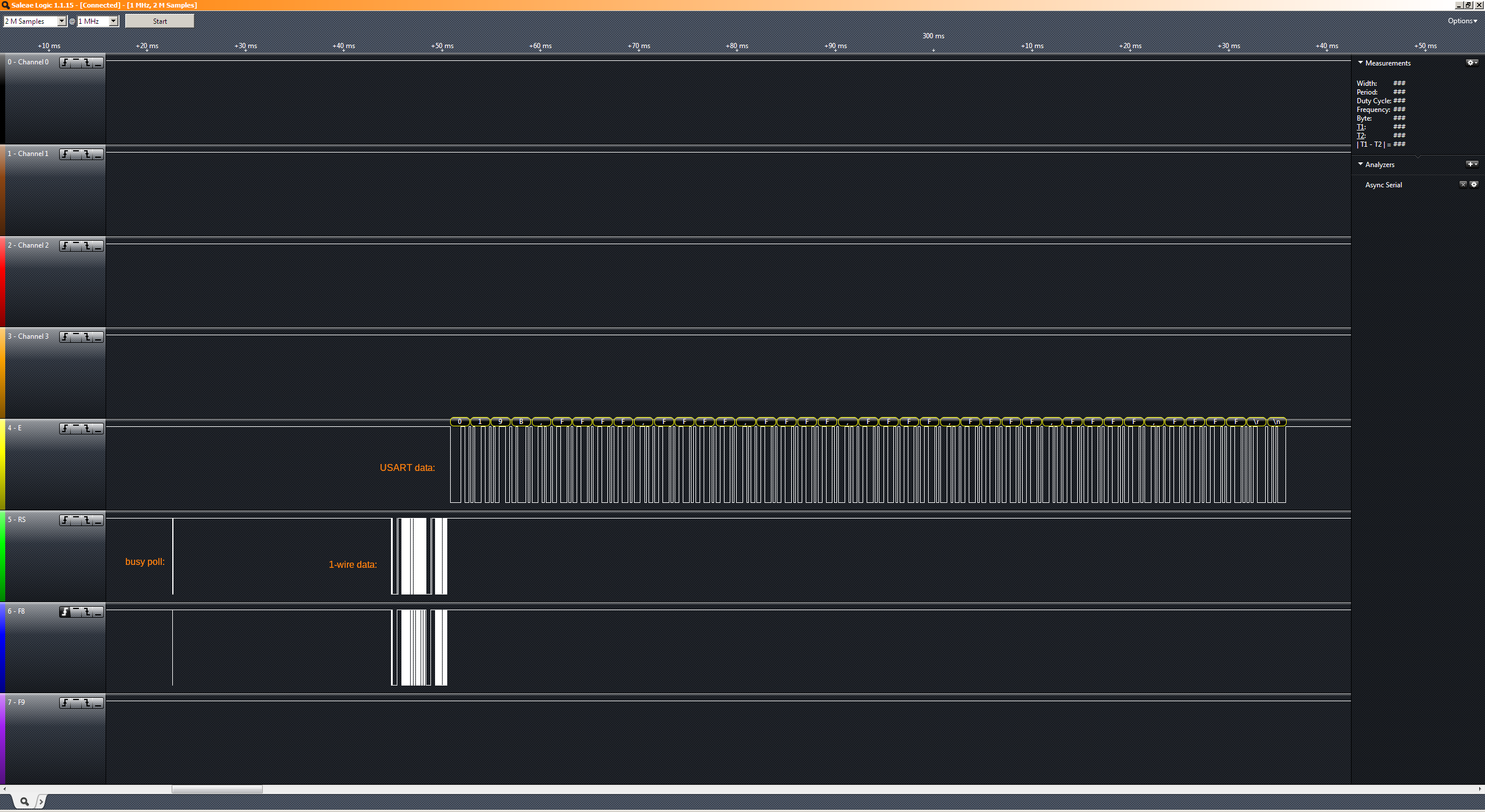
Closeup of an UART telegram. Only one sensor is connected, that's why the other values are FFFF.
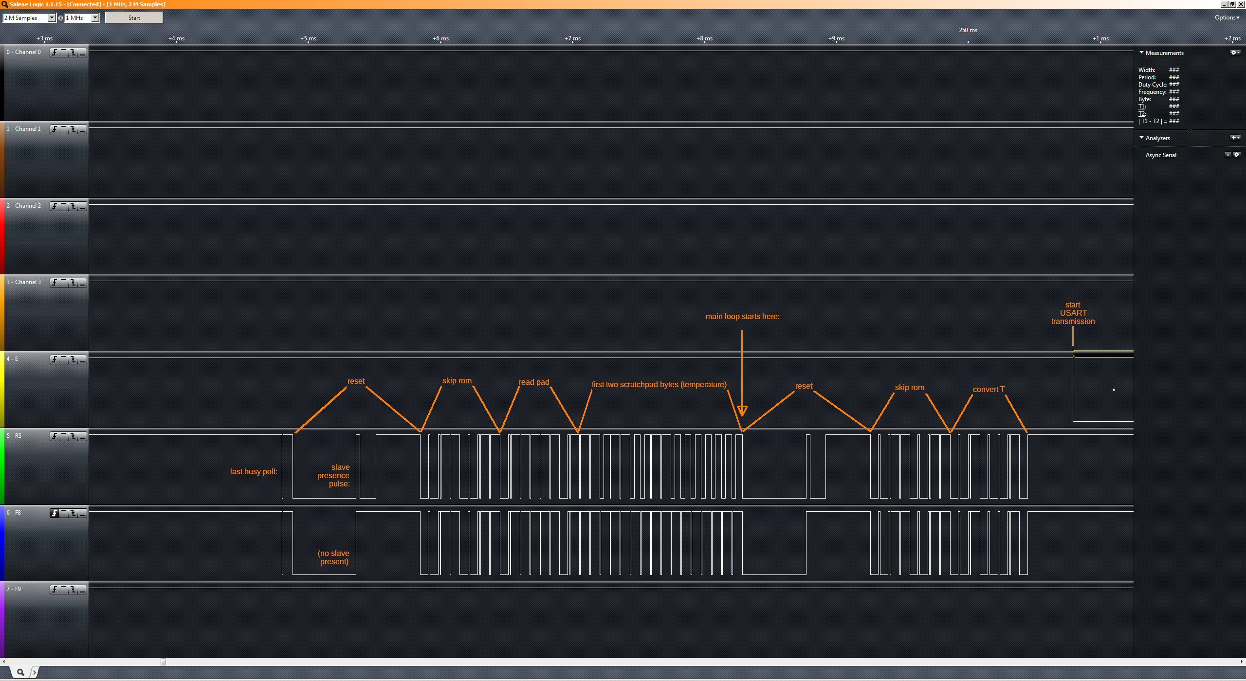
Here you can see the two far-stretched reset pulses, lasting almost a millisecond each. On the green channel you can see the presence pulse that the sensor sends in response. The blue channel doesn't have a sensor connected and thus shows no presence pulse. Note that the second reset pulse in the screenshot is actually where the main loop starts. This is why the buffer for the very first UART transmission is still empty, but it makes for a neater loop design 8).
Some real data
Here is a little bash script to capture the data, convert it from hex into human readable numbers, print them to the screen, and write them to a csv file, including time stamp. You'll need to have bc installed for the floating point math.
#!/bin/bash

# Function to convert signed 4-figure hex value to decimal.
# 000F = 15
# FFF0 = -16
twos() { x=$((16#$1)); [ "$x" -gt 32767 ] && ((x=x-65536)); echo "$x"; }

# Output logfile. Data will be appended.
csvfile="ds18b20uart.csv"
# Which TTY device to use. Change accordingly.
ttydevice=/dev/ttyUSB0

# Setup the TTY
stty -F $ttydevice 4800 raw

# Save to file:
echo -e "Timestamp,Time,Boiler,Group,Ambient" >> $csvfile

# Loop through the lines received. Stop by pressing CTRL-C.
while IFS= read -r buf; do
	IFS=',' array=($buf)
	# Print to screen:
	echo -e $(date +%T) "\tBoiler: " $(echo "scale=4;$(twos ${array[0]})/16" | bc) "\t\tGroup: " $(echo "scale=4;$(twos ${array[1]})/16" | bc) "\t\tAmbient: " $(echo "scale=4;$(twos ${array[5]})/16" | bc)

	# Save to file:
	echo -e $(date +%s.%N)","$(date +%T)","$(echo "scale=4;$(twos ${array[0]})/16" | bc)","$(echo "scale=4;$(twos ${array[1]})/16" | bc)","$(echo "scale=4;$(twos ${array[5]})/16" | bc) >> $csvfile
done < $ttydevice
For the following example, I hooked up three sensors in total, and put two of them on my La Pavoni Europiccola coffee machine. The third sensor was just lying there on the counter and recording the ambient temperature.
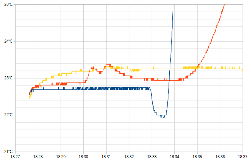
This is a detail of the start of the measurement. The yellow trace is for the ambient sensor. Since it is just dangling in free air, it shows the most amount of self-heating. The sensors are basically running at almost 100 percent, so this is to be expected. To avoid this, you'd have to use a much lower duty cycle and only take one reading every minute or so.
The blue trace is monitoring the boiler temperature. You can cleary see when I added some (cold) water to the tank and then switched on the machine.
The red trace shows the sensor put up against the group head. The two little bumps around 18:31 occurred while I was adding two strips of capton tape over the sensor, to guard it a little against disturbances due to air currents.
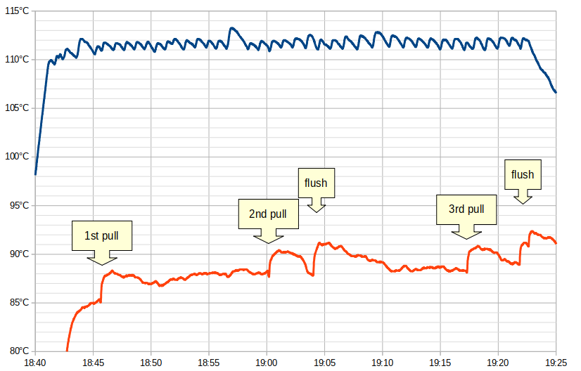
Here is the full plot of the hot machine, annotated at the points when I pulled the actual shots. The blue trace from the boiler nicely shows the action of the pressostat kicking in and doin' its thing. The hysteresis of +- half a degree is pretty good actually; a simple mechanical thermostat would not regulate that well. The three bigger excursions show when I was ''bleeding false pressure'' and releasing some steam (and thus pressure) from the boiler through the steam wand.