24V Lead Acid Battery Balancer
The other day I decided that I finally want a battery balancer for my small PV setup. I am running a 24V system on two 12V 100Ah AGM batteries. They have been on duty for the last two years and thus endured more than 700 cycles (down to about 50% SOC) already, which is plenty for that type of battery. But it is starting to show. After several weeks of overcast weather, on a sunny saturday, I noticed that the regulator was only delivering about 50% of its maximum capacity, when I was expecting it to max out at 100% to replenish the mostly empty batteries. So I took out the multimeter and measured the battery voltages during the absorption phase (which is configured to deliver 14.6V per 12V-battery): It read 14.9V for one of the batteries, and only 14.0V for the other one!
Like I said, the batteries are pretty much used up by now and will get replaced anytime soon, but I figured why not give the balancing approach a try? And I will keep it for the next set of batteries anyhow, maybe yielding an even longer lifetime for them when using it right from the start.
Update after 3 months of use: The balancer is working great, and I am able to reach 85% regulator power output again! New batteries are ordered now.
So I searched the Internet for some circuits to try. After learning that there are active and passive methods to balance the cells, I deliberately settled on the passive approach. Sure, it will waste some energy into heat, but in my case that's fine. Usually the two panels generate much more power than the battery can take up over the course of the day.
The active approach works by taking excess power off the stronger cell and store it in a capacitor or inductor, and then put that energy into the weaker cell. I am not so sure if that would actually work though, in case one of the batteries has too high of an internal resistance and doesn't accept the offered energy in time or at all. So instead of balancing the charges, nothing would actually happen. Might just as well only be FUD on my part, though.
Most of the passive designs work by switching a power resistor in parallel to the stronger cell with a transistor, once the voltage difference between the two cells exceeds ~100mV. I didn't have any suitable power resistors at hand, so I let some MOSFETs do all the work and dissipate up to 20W each. A shunt and an NPN make for a cheap current limiter and work like a charm. Another thing that I added was a ''brown-out'' below 27.3V, so that the balancer is only ever active during charging. Imagine one cell in one of the batteries goes dead; you really don't want the balancer to pull the good battery down to 10V every night, without you noticing...
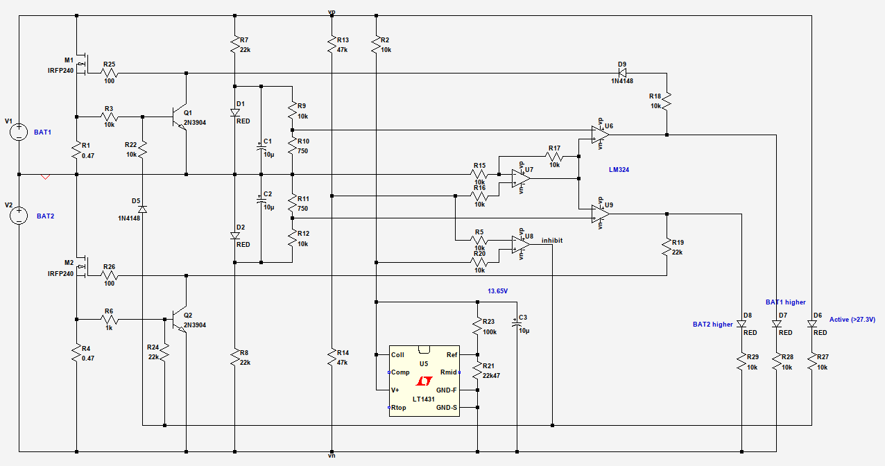
The balancer schematic
Circuit Description
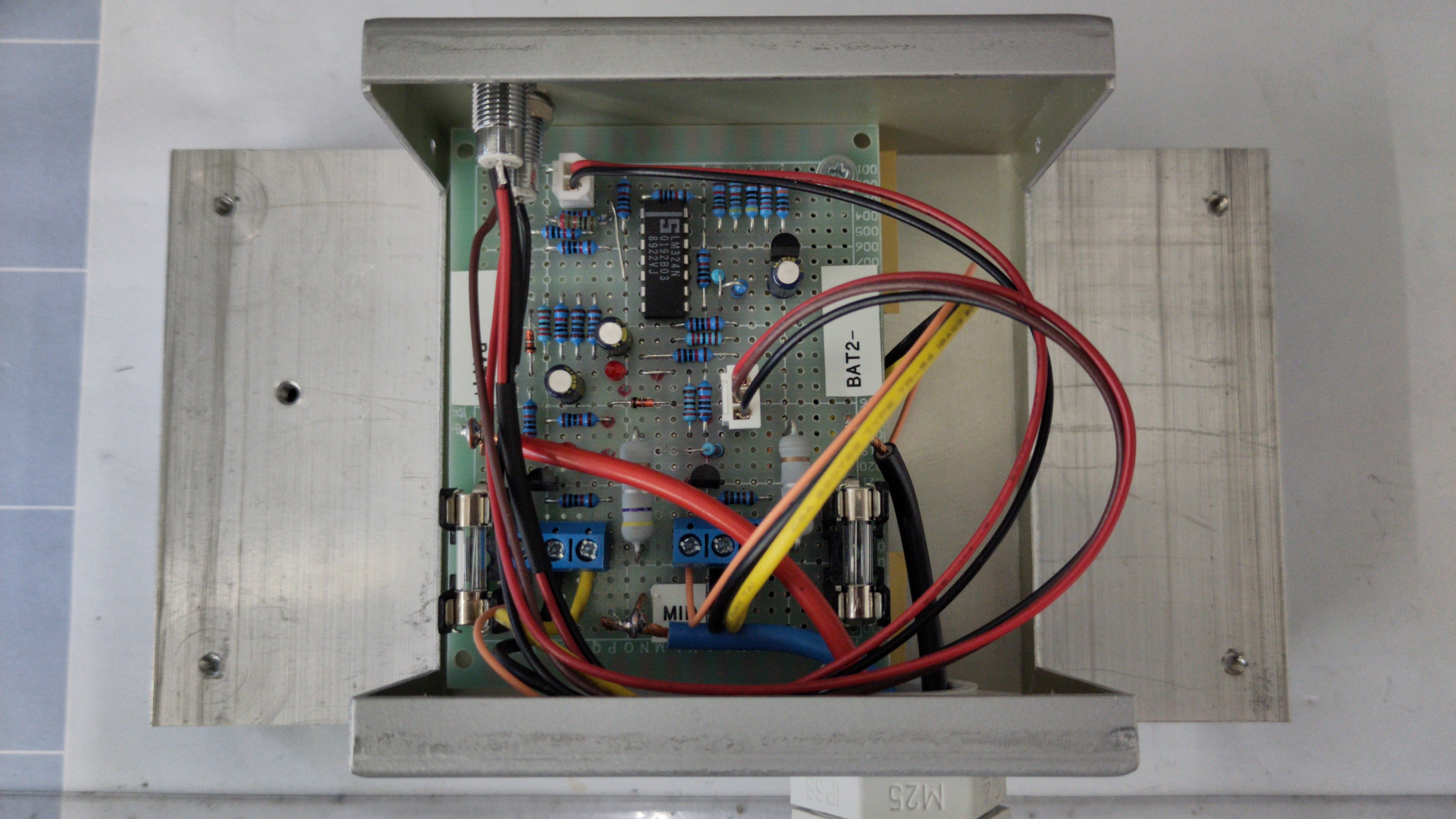
M1 and M2 are the two power semiconductors and mount on the same heatsink. There's only ever one of them active, so no need for separate heatsinks as long as the one is big enough. You can use pretty much any type of MOSFET here that can handle the power dissipation. I used some recycled IRFP460 with their big TO-247 case, but things like IRFZ44 in TO-220 should be fine, too. Most of the specs like Gate Charge, Vgs-on and Rds-on are not important, it just has to be able to survive the battery voltage and a couple of amps. R25/26 are gate stoppers and solder directly to the gates of the MOSFETS to avoid oscillations, the value is not critical (47 or 220 ohms will do as well). R1/Q1 and R4/Q2 are the current limiters for the MOSFETS. Without them, the FETs would dissipate as much power as they can get, which would certainly lead to a RUD (rapid unscheduled disassembly). You can adjust the resistors for a different maximum current, like 1 Ohm for ~0.6A or 0.22 Ohm for ~3A, obeying their power dissipation (0.22 Ohm will approach 2W). I used 0.47 Ohm for about 1.4A. R3/R6 limit the base current, the values are again not overly critical. I have tweaked them a bit so that they don't interfere with the inhibit signal applied via R22/R24, as this should take precedence. Speaking of which, the inhibit signal drives the bases of Q1/Q2, and thus disables the MOSFETS, as long as the total supply voltage is lower than ~27.3V. D5 is there to protect Q1 from a negative Vbe, just like D9 does for the drive signal. U5 together with R2/21/23 form a voltage reference for the inhibit signal, set to 13.65V. R2 has to maintain a current of ~1mA through U5 all the time, lest it drops out of regulation. U5 is a bog-standard TO-92 TL431 actually, with the LT1431 used only for the convenient spice model. R21 consists of a 22k and a 470 Ohm resistor in series, yielding a very useable reference voltage value with standard resistors out of the parts bin. That voltage is then compared to half the total battery voltage, measured by the divider R13/R14. U8 is working as the comparator here, D6 is the corresponding (optional) indicator LED. It lights up as long as the voltage is high enough and thus indicates ''I am active now''.
D1/D2 with R7 through R12 form two more voltage references, each set to ~100mV from the common point of the two batteries. They determine the allowed voltage difference between the two batteries before the balancer kicks in. They don't have to be exactly equal and the actual value is not critical; 100mV seems to be a common value used elsewhere, too. I used 500 Ohm for R10 and R11, yielding closer to 70mV. R7 and R8 set a current of ~0.5mA through the LEDs, which should be plenty.
U6/7/9 form a window comparator, which compares the ''theoretical'' mid-point of the batteries (divider R13/R14) to the ''actual'' common point of the batteries (which is flagged as Ground in the simulation), with a ''window'' of +-100mV. So, if the ''theoretical'' mid-point does not diverge more than 100mV from the common point, both batteries are considered equal and none of the outputs of U6 and U9 is active. Let's assume now that the upper battery, BAT1, has a significantly higher voltage than BAT2. This will shift the measured voltage at the mid-point of R13/R14 a little higher than Ground, higher than the 100mV reference, and finally set the output of U6 high, which will then drive M1 through R18 (current limit) and D9 (reverse voltage protection). Depending on the internal resistance of the batteries and their wiring, the MOSFET will not kick in hard and immediately draw the maximum current. So if the threshold is set to 100mV and the batteries differ by 102mV, there will only be a couple of milliamps flowing through the FET, gently keeping them to within 100mV of each other. If there is a bigger difference in voltage, maybe due to a sudden power surge demanded from the batteries, the balancing current will rise accordingly until the maximum is reached. It will stay in that range and happily dissipate power until either the differential falls below 100mV or the total battery voltage falls below 27.3V to avoid a deep discharge of the batteries. LEDs D7 and D8 are again (optional) indicators. I have used a dual color LED in my build, just because I had one handy.
The whole circuit will draw a couple of milliamps in standby all the time. You could try and optimize that a bit by using a micropower quad opamp instead of an LM324, a TLV431 instead of a standard 431 and adjusting R2 accordingly, increase R13/R14 for even less current through the LED references, do not use the indicator LEDs (which will indicate a significant difference even when the balancer is not active), or decrease the MOSFET drive currents by increasing R18/R19. Since the gates do not need any sustained current, most of the drive current will end up being dissipated by Q1 and Q2 anyhow. Just make sure to maintain a stable margin by not starving all the currents to an absolute minimum, which might lead to flaky and unreliable behaviour under certain conditions.